
We’re getting more and more active in the operando measurement of battery materials. That means we need to electrically charge and discharge the materials with a battery cycler while we’re measuring it. Until now, we’ve been using a separate battery cycler for this, run completely independent of the SAXS/WAXS measurements. That set-up is unsatisfactory, however: it does not easily allow linking of the data and it does not let us synchronise and control the X-ray scattering measurements with the cell state. A different solution was needed, and in accordance with our principles, we went a little overboard in the implementation.
TL;DR, or “the Executive Summary”
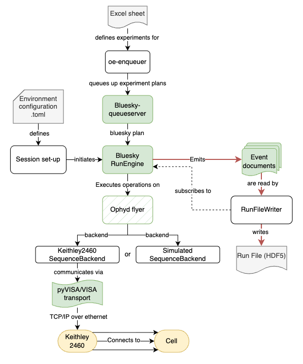
When we want to do operando measurements using an electrochemical cell, we can now set up and synchronise a Keithley 2460 sourcemeter (also known as a Source Measure Unit (SMU)) to provide the necessary voltage- and current- driving- and sensing operations.
The sourcemeter can then autonomously execute particular tasks (e.g. constant current, constant voltage, pulsed charging/discharging or sweeps). On the user-facing side, it can (optionally) be programmed using an excel sheet where every row contains the task plan, just like we do for the MOUSE instrument.
The information in the excel sheet is then converted to bluesky plans for the bluesky orchestrator (Run Engine), and queued up in the bluesky queueserver. The plans are then executed one-by-one, either immediately or started after arming using an external hardware trigger.
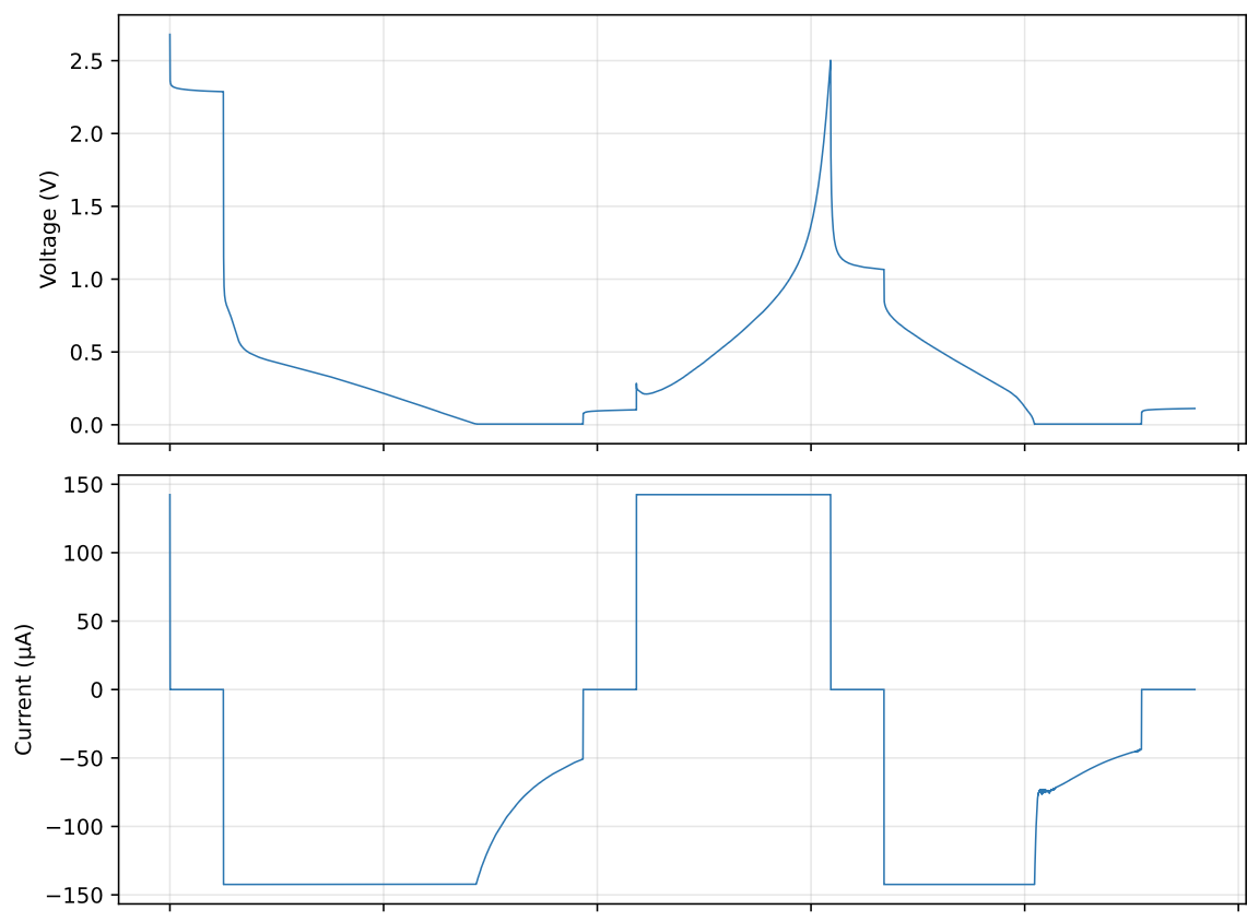
Tests using this set-up so far on some prototype cells have shown solid performance, with good accuracy, and good adherence to the preset operating limits.
Soon, we will do a synchrotron experiment with this, after which we will start integrate this sourcemeter set-up (with its own bluesky queueserver) into the MOUSE instrument for synchronised automated electrochemical experimentation, with consistently linked experimental documentation.
For those who like details, do read on 🥰:
The Fast, not cheap and not so good solution: the Market Leaders
Before we come up with a separate solution, we checked what pragmatic solutions would be available. The standard cyclers from manufacturers such as Biologic and Gamry are omnipresent in the various battery labs, so we looked at those for a bit. These not only do cycling but can also do impedance spectroscopy (EIS), giving you a bit more insight into the materials under investigation. Ideally, our Bluesky experiment orchestrator would be able to control the hardware and read them out over a network connection via a bespoke Ophyd device abstraction layer.
Now, there are Windows DLL’s available for these two cyclers that in theory allow communication with the hardware (DLLs are closed source, dynamically loaded Windows binary libraries to interact with the hardware). These DLLs allow you to configure, trigger and read out the hardware in, say, a LabView or Python script. But that is not a suitable solution for us, as it would require a separate Windows server to be installed at and integrated with the machine. This brings a heap of extra maintenance workload, adds additional points of failure, and would require us to come up with a bespoke communication protocol to communicate between the experiment orchestrator and this Windows machine (low-latency control and data transfer). Using windows emulators like WINE or virtual machines may work, but it remains a fragile and maintenance-heavy ecosystem. Lastly, the closed-source DLL means you’re at the mercy of the manufacturer’s support timeline. If they decide to drop support, you’re stuck with an increasingly fragile, outdated Windows machine. I think we all have laboratory instruments on Windows 2000 and older, transferring data with floppies and USB sticks, demonstrating how “well” that works in the long term…
The better solution would be to have a well-documented interface protocol. For decades, we’ve had a very wide range of such standard protocols available for communicating with test and measurement (T&M) instruments, that document how to address, control, and read instruments. The older such protocols include SCPI, the current ones include LXI and HiSLIP. Broadening the scope to generic instrumentation we also see SILA 2 and OPC-UA, to name but a few. Each somewhat overlapping yet focusing on different needs, but all born out of a desire to make standardised sense out of the communication and interoperability chaos.
After asking around for a bit, it looked like at least for these two manufacturers, such interoperable communication protocols were neither present nor planned. We did contact some smaller instrument manufacturers who were willing to implement something based on communication over ethernet sockets (which deserves to be lauded), but this would not be implemented and robust on short timescales.
[note: I’ve just now found out about Zahner, which could also be an option.]
The Cheap, Good but not Fast solution: open-hardware cyclers
Ideally, we’d move away from commercial suppliers for cyclers, and use in-house built, open-hardware cyclers such as PolArStat, MYSTAT, DStat or WattRex (though there are many, many more designs out there worth evaluating). These are typically focused on minimising cost, and usually rely on Arduinos or Raspberry Pis for the direct control. They generally don’t do impedance spectroscopy, and are usually limited to a single voltage- and current range, but if you are investigating one particular chemistry in one particular cell design, then these will do just fine.
They will work for a tiny fraction of the cost, their open hardware designs are eminently suited for reproducible scientific research purposes, and they are inherently fully controllable (with more or less effort, depending on the quality of the accompanying software). For us, these were initially interesting, but there were some limitations making them less ideal for our direct application:
- we needed very fine control down to low voltages and very low currents, that can run stably over a long time.
- for the upcoming beamtime, we needed a solution within a relatively short timeframe to have time to develop the bluesky interface for this
- Since we’re human and often make mistakes (especially at long beamtimes), we need a system with at least some protection built in against stupidity. The open hardware cyclers are good, but I’m thinking protection against overvoltage/overcurrent, accidental shorts, thermal management, maybe some protection in the form of optocouplers to protect the triggers, some internal fault diagnostics, and so on.
In essence, we’re looking for an open hardware cycler where low-cost is not the main driving factor, but rather one that focuses on quality, range and robustness (and ideally one that I can buy from somewhere to save on the build time). I’ve not found one of these yet.
The Fast, Good, but still not cheap solution: a sourcemeter
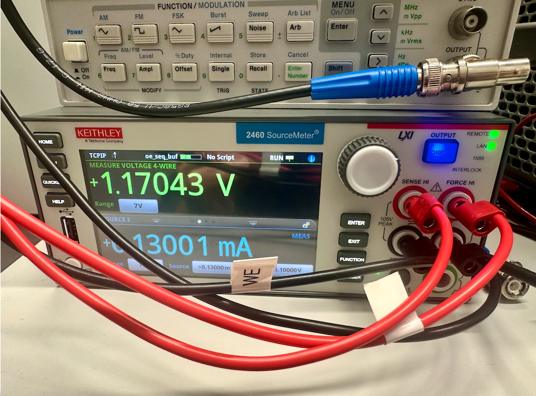
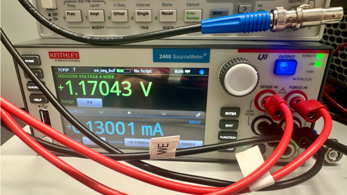
So for now, we’ve fallen back on solution number 3: using a commercially available sourcemeter for this. These are lab bench test devices that can precisely supply a (positive or negative) current or voltage, and accurately measure its counterpart. These cover most of the same functionality of a battery cycler, but with a high dynamic range (actually a superposition of multiple ranges), a higher measurement precision than a standard cycler and some more flexibility in the type of electrochemical experiments you want to carry out. They lack the ability to do EIS, can only do one cell at a time, and don’t have things like battery safety monitoring integrated by default.
There are various sourcemeters on the market, and we’d converged either on a Keithley 2460 or a Rohde & Schwarz NGU411. Unfortunately, the latter is not able to measure an open circuit voltage (or a voltage at zero current, the NGU411 has a minimum current of +/- 20 µA). So to the Keithley we went.
The control set-up
Hardware connections
So, with the sourcemeter in hand, we now had to come up with a good, future-proof way to control it. On the hardware level, it just connects to a machine network with an ethernet connection over TCP/IP with (optional) DHCP, no problem. It communicates in an LXI-compliant way over VISA, so we know how to talk to it. We also attach a +5V START trigger signal and monitor three digital signals emitted from the sourcemeter: READY, RUNNING, and MARKERS (for recording timing signals if needed).
Sourcemeter runtime code
The sourcemeter has broad functionality, which we set it up for more autonomous operation by loading custom sourcemeter programs onto it. These can be used as building blocks and internally sequenced. These are written in a modified LUA 5.0 language called TSP. We’ve set this up so that the basic functionality (potentiostat/galvanostat operation, pulsed charging/discharging, buffered reads, internal or external triggering and external status signals) is covered by these blocks. This internally-driven operation means that, once a program is loaded, the sourcemeter can operate independently of the rest of the hardware, and no timing-critical functionality needs to be externally provided. In practice, I can set it going, pack up my laptop and go home, returning the next day to reconnect, retrieve the data from the device buffer and continue.
The sourcemeter as an Ophyd flyer
This internally driven behaviour works very well with the Ophyd “flyer” abstraction class: the experiment orchestrator configures the device, arms it, triggers it using an internal or external signal, and then sits back and reads out the data whenever convenient as the device runs autonomously. This is the same functionality as what you’d use for motion flyscans (as opposed to step scans), or for hardware such as temperature controllers.
For fun and testing, this Ophyd flyer can either use a real Keithley2460Device as a hardware communication backend, or use a simulator. The simulator has been configured to respond exactly like the Keithley does, so we can test, for example, how the Ophyd flyer would behave if the communication drops out mid-stream, or how the Bluesky plans behave when the voltages would hit a preset operational limit. The Ophyd flyer itself for the Keithley is available here: https://github.com/BAMresearch/keithley2460_ophyd
The experiment orchestration layer
With the Ophyd flyer, we can now move to the orchestration layer: the Bluesky RunEngine. This orchestrator runs experimental “plans”, i.e. sequences of steps, that handle the set-up of the flyer and reads the document stream from it. It also gracefully handles what happens when we want to — or have to — interrupt. A plan can be, for example, a constant-current charge with a constant-voltage step at the end.
The run engine sends out a document stream with the experimental metadata, and things (events) that are happening on the device. There is then a “RunFileWriter” that subscribes to this document stream, creates an HDF5 file in SWMR (single writer, multiple reader) mode, and updates it as data continues to come in. When the RunEngine emits a “stop” document, the RunFileWriter finalises and closes the file. The internal information structure in the HDF5 file is structured to resemble the NeXus structure (“NeX-ish”), to help us couple the information in the (sub-)tree to that of the SAXS/WAXS measurements.
And a queueserver on top
When we want to subject an electrochemical cell to to multiple charge/discharge cycles, with different charging styles or rates, we now prepare a series of plans and queue them up with our pluripotent friend, the bluesky queueserver. This is a queueserver in the traditional sense, in that we prepare our plans with the use of an excel sheet, and queue the plans up in the queue. They then get run one-by-one. You can reorder or adjust the queue to your liking if needed, and the queue keeps track of what the result was of everything that ran.
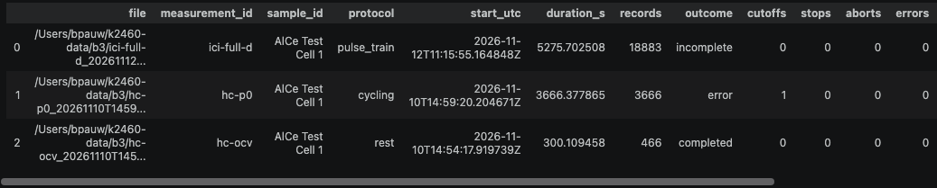
As mentioned before, the bluesky queueserver also provides the operational framework, or “environment”: it handles the startup of the sourcemeter, sets operational limits (current limits, voltage limits, times), and dictates which plans are allowed to run on this particular cell. So in this case, you would have a separate environment per electrochemical cell, to provide safeguards that your sourcemeter plans can run safely for the attached cell. The bluesky RunEngine and queueserver set-up for the electrochemistry experiments is available here: https://github.com/BAMresearch/electrochemistry_bluesky
Testing, testing, testing
Hardware test-bench
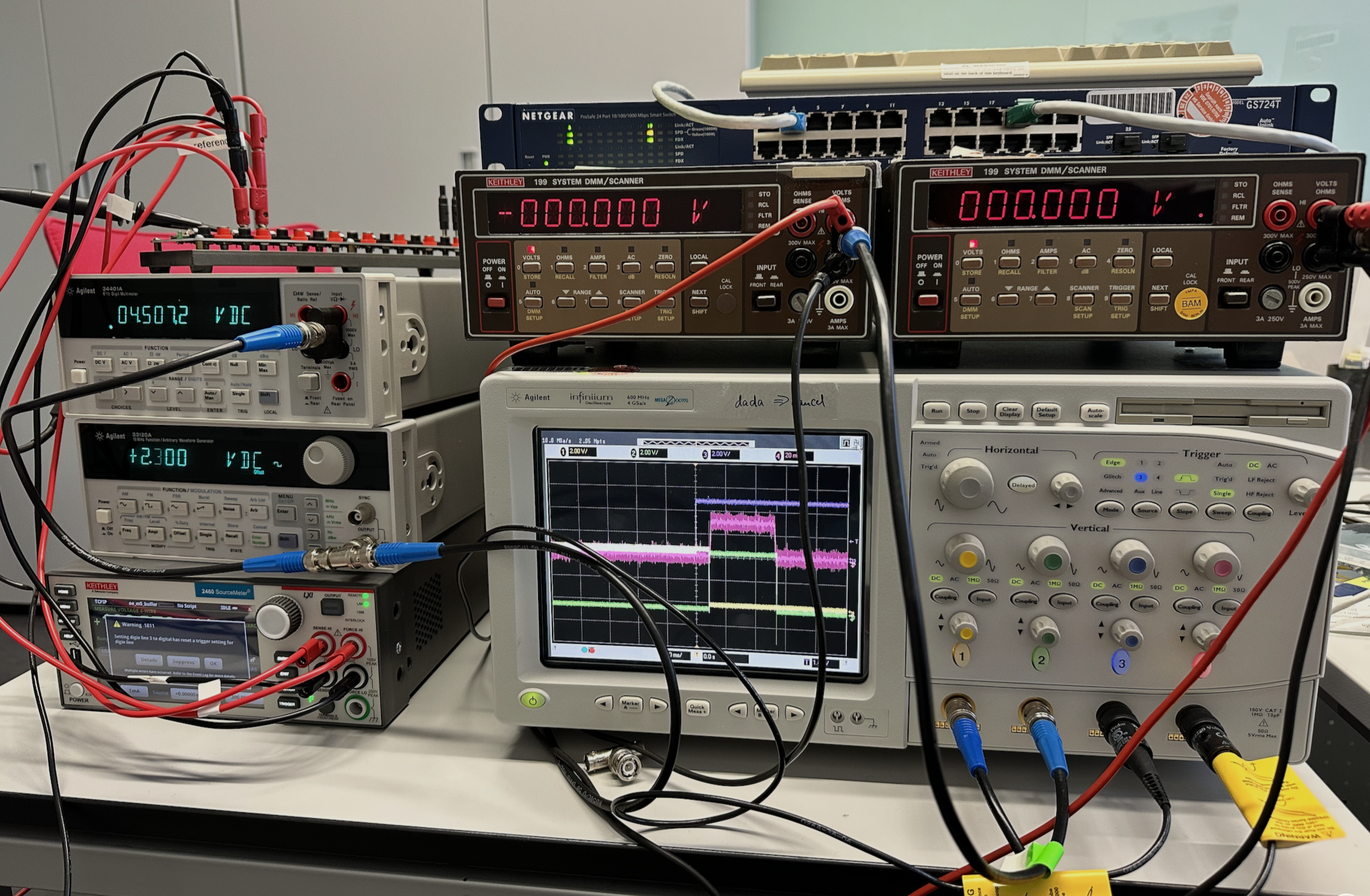
To make sure the sourcemeter was doing what it says it’s doing, and to get a grip on the timing with hardware and software triggers, we built up a testbench. Over the years, I’ve made a bit of a collection from some older T&M devices left behind by retiring colleagues, which has now come in handy. We’re so well stocked that, when the high-speed oscilloscope went “bang” while emitting some magic smoke — this is second-hand equipment after all — we could simply pick up the next high-speed oscilloscope and continue without missing a beat.
But we built a set-up with a signal generator to generate a trigger signal, a multimeter to double-check its levels, two more multimeters to read out the sourcemeter’s “READY” and “BUSY” signals, and an oscilloscope to check the delay between the trigger signal, the rise of the BUSY signal, and the first MARKER signals arriving, in addition to monitoring the actual voltage drop over the 100 Ohm test resistor.
Testing on real cells
After making sure we could enqueue bluesky plans on the sourcemeter, trigger them and get trustworthy readouts with the test resistor, we moved on to testing coin cells loaded with the anode side of a battery. This allowed us to test that the sourcemeter with the internal runtime would support long, autonomous multi-step runs, whose measurements could be retrieved days later. The retrieval method now also appends the retrieved data to the partial HDF5 run file that is constructed at the start, so that a full archival-quality file exists, festooned with all the metadata you could possibly eat.
Real cells also allow us to refine the plans for the beamtime, which is a process that is likely to continue until the actual beamtime. With nothing on the line, we can play around within the charge envelope to see what would be interesting regions to explore, and prepare some protocols for the experiment. Hopefully, we’ll have fewer surprises at the beamtime itself.
Fun with LLMs
The aforementioned Ophyd abstraction and queueserver set-up for the electrochemistry experiments has been developed with the help of LLMs, leveraging the same foundation and test-heavy design as we have for the MOUSE-bluesky packages. As we mention in the McSAS3 paper acknowledgments:
“Parts of the code were implemented with the assistance of OpenAI Codex and were reviewed and tested by the authors. We are aware that tools of this kind are built on knowledge and code contributed by people who were never asked, and who cannot be credited individually here. We thank them nonetheless.”
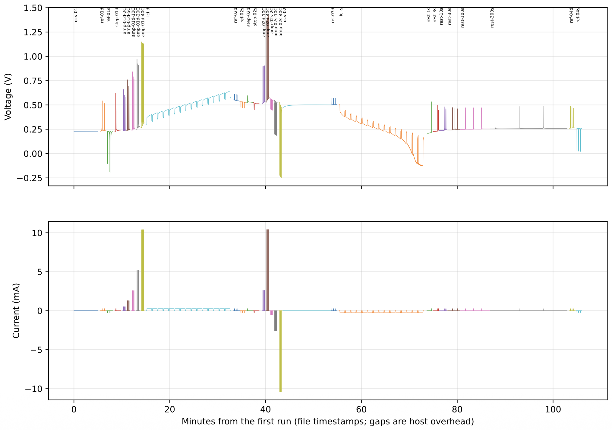
For this project, I pitted Codex against Claude, and analogous to the Swiss-cheese model of accident prevention, the different LLMs are able to complement each other’s oversights.
More fun ensued when I allowed the LLM access to the machine network (with only the sourcemeter on it), and letting it construct and execute bluesky plans by itself. Given the limits implemented (and thoroughly tested) in the ophyd framework for this device, I was confident that it would stay within the voltage- and current limits for the cell under investigation. With a simple prompt, along the lines of “characterise this cell, stay within the operational limits, you can use CC, CV, OCV and pulsed (dis-)charging to characterise the cell, you have two hours.”, it went off and sent around 50 different plans via the queueserver to the sourcemeter. The outcome was, to my layman electrochemical eyes, a halfway decent report characterizing the cell with some okayish initial findings.
Coming next…
Beamtime
In December, we’re going to bring this stuff to the CoSAXS beamline at MAX-IV. This will be the first time that I will experience that beamline, so I’m very curious to find out what it can do. Since they’re not running bluesky for some reason, we will be relying on our own bluesky (queue)server, coupled with beamline hardware triggers for the operation and timing of the sourcemeter. Nevertheless, I expect to see some cool results come out of that, hopefully something that can be rolled nicely into a short publication.
Future integration in the MOUSE
During the NOBUGS conference, I was informed that the best way to integrate these complex devices into an experiment is to run with multiple queueservers: one “leading” queueserver (that would be the MOUSE instrument one, and “follower” queueservers for the attached devices. The leader makes sure that each sub-part of the experiment is running the right plan for their part of the experiment, and sends a start signal (either by hardware or software) when the time is right to move. This allows for the “super-orchestration” of many components in complex experiments. That is not yet something I have played around with yet, and this will be the first.
First though, we’re preparing this thing to bring along to a beamtime, wish us luck!