

Today we had the new X-ray source arriving. It’s not working yet, but its imminent arrival spurred me into action to mount the Ultra-SAXS components in place and do some minor maintenance…
We have two new motor stages used in version 2 of the instrument (Figure 1). These are a rotation stage to replace the upstream crystal rotation (which does not need to be so precise due to the incident beam divergence), and a stage to move the detector back and forth. Why would I want to do that?
The reason for moving the detector has to do with alignment. Every 4-bounce crystal that is inserted into the beam moves the beam by a few millimeters. Therefore, when we are aligning the collimation, the detector is at position y=0, insert the upstream crystal (for alignment), and it is at y=3.5 (or so). Insert the downstream crystal and it moves to y=7. When you then want to adjust the upstream crystal again, the detector needs to move back again, and it all gets tedious after a short while. So motorize, and alignment can be done without much headache.
Furthermore, the rails underneath the stages should allow me to move the crystals in and out reproducibly, further easing alignment.
So this week, I had to connect the motor cables to the motor controllers, program the controller to not burn out my motors, and test the limit switches. Things turned a bit annoying when my soldering iron didn’t want to work properly (thermostat issues), and when Kohzu supplied a useless motor wiring diagram.

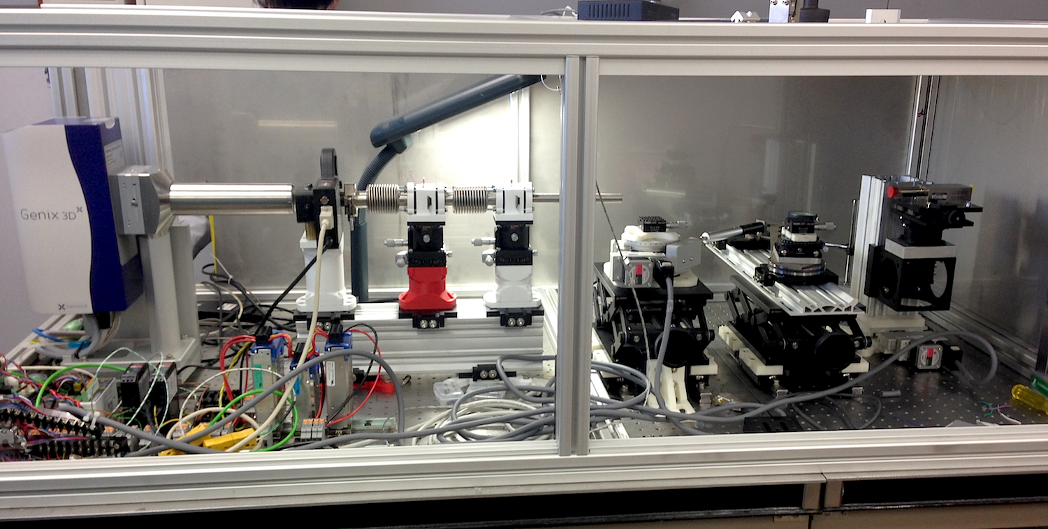
Now everything is in place (Figure 2), except for the new SDD detector electronics. The detector requires a set of voltages to power it that I do not have at hand (0-3V and 300V, which I have, but also a stable -9, +9V, which I do not have). Furthermore, the pulse analyzer for the detector is still missing, hopefully to arrive soon (after which I have to program a communication script and see if everything is working).
Fortunately, I didn’t burn out the motors (yet), and everything moves the way it is supposed to. Now we wait for the detector electronics to arrive, and the source to fire up, and then follows either a scream or a cheer from Tsukuba. Let’s hope I got things right for this version too.
Leave a Reply