
Herewith I’d like to present the results of some brainstorming on a sample holder design. This concept design is to be build soon, so if I can, I’ll make the design drawings available as well. If anyone has ideas for improvement, I’ll be happy to implement them (under the Creative Commons noncommercial sharealike license).
My reason for publishing these images is to have others save time if this sample holder suffices for their task. Many people are designing sample holders by themselves, taking up time that could just as well be spent on something more “front-line” in terms of research. I have selected the Creative Commons license, because I want to involve people in the design, and enable the use and evolution of these sample holders in research. I do not want companies to make loads of money on it, instead they can choose to supply it for manufacturing costs as an additional bonus option to their machines.
Enough of the legal considerations, on to the practical.
In my design, the sample holder conditions were:
– Easy loading of samples
– Multiple samples per sample holder
– A variable sample thickness from 0.5 mm up to 2.
– Controlled heating.
The design that I conceptualised with useful comments from Karsten D. Joensen, Jens W. Andreasen, Kell Mortensen, Martin E. Vigild and Enno Klop are depicted in the figure below:
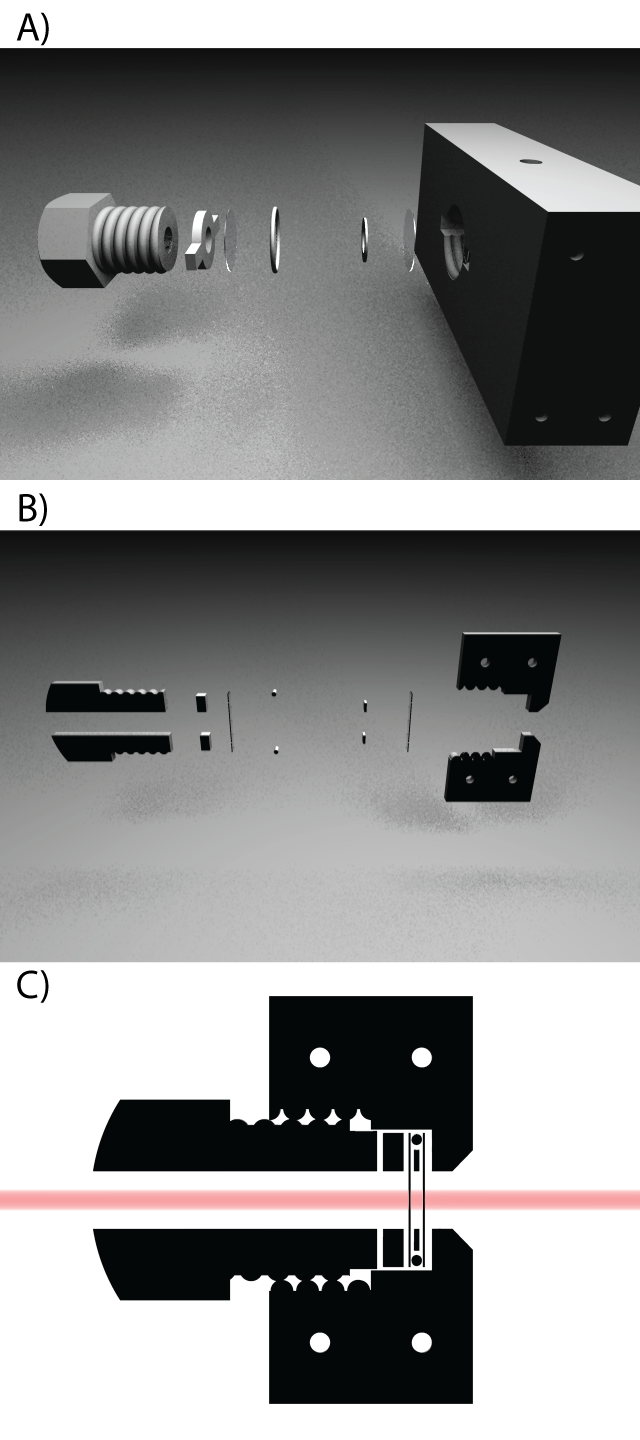
A) shows an exploded view of one cell in the sample holder. The materials envisioned are teflon for the bolt, torque remover ring, and spacer ring, mica for the windows and an o-ring of a suitably inert material, such as Viton.
The torque remover ring purpose is to remove screw torsion on the mica windows when mounting the samples. It is not known whether this is absolutely necessary, but it could prevent creasing of the mica.
The spacer ring (inner disc-like ring) has the thickness required, and prevents the forces from becoming too large on the o-ring and sample.
The main mounting plate as illustrated, only has one sample position, but one could imagine more sample positions next or above one another. The plate furthermore has four holes through it that can support a heating wire, and a hole on the top for mounting a thermocouple. Liquid cooling is another option, but would require a slightly more bulky main plate.
B) shows a cross-section of A), which highlights the opening angle of the exit hole, and the grave in which the sample rests. The maximum angle for this model is 45 degrees, but could be made larger depending on the material of the main plate.
C) shows a cross-section of the un-exploded sample holder. A (red) one millimeter beam is drawn in for comparison purposes. The threads on the bolt are supposed to line up with that of the main plate, naturally. The sample holder main plate could be chosen thinner, for more convenient loading of the sample. In this design, it is a 1 cm. thick plate.
As said, more information on this design will follow if possible. Any comments are always welcome.

This work is licensed under a
Creative Commons Attribution-Noncommercial-Share Alike 3.0 Unported License.
Leave a Reply