

Together with Dr. Petzold from the HZB, we have devised a solution for measuring the transmission factor in the Anton Paar SAXSess system (the problem is detailed in this post). Details are as follows:
To determine the transmission factor, we are using a thin iron foil placed in the beam between the sample and the detector. That iron foil fluoresces when irradiated, and the fluorescence gives a nice strong signal on the detector. This fluorescence signal should be proportional to the flux in the direct beam. In essence, this works in the exact same way as we used before: see Figure 1, and the derivations in this post, replacing the thick glassy carbon with a thin iron foil. As before, you need an absorber to prevent the photons scattered by the sample from reaching the detector (a piece of lead tape will do). So how do we do this in our instruments?
For this purpose, we needed to design an additional component for the instruments. Fortunately, both Dr. Petzold and I use the exact same flavour of instrument in our labs (the Anton Paar SAXSess II). That means that with one design of iron foil holder, we could have a fix for both instruments, and for a potentially much wider audience as well. The idea was to have the iron foil mounted on a slide, which can be slid into place when a transmission measurement is to be done. Since the beamstop is quite fragile, it would be best to have this some distance away from the beamstop, and designed in such a way that the construction cannot fall onto (and damage) the beamstop. Onwards to making the device.
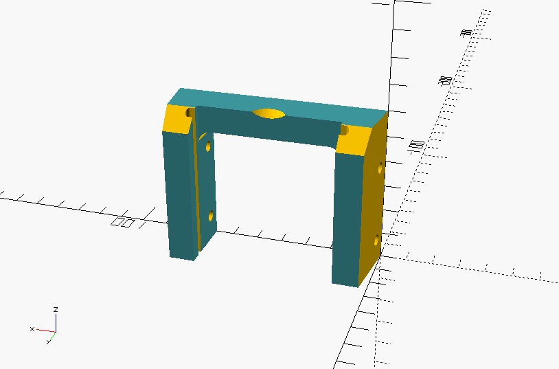
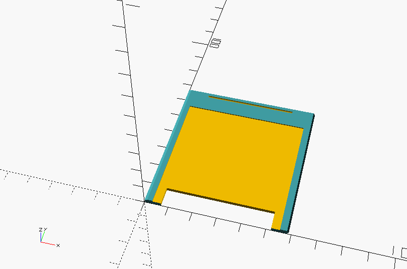
Using the rapid prototyping possibilities of the 3D printer, we designed and printed a bunch of holders and slides in quick succession (at a rate of about one version per two days). After five versions, the design was sufficiently evolved for integration in the system (Figure 1). This fits snugly in the tapered section of the housing, can be fixed with set screws, and has additional features to easily set and remove the slide (Figure 2). Furthermore, it can hold the slide with additional shielding facing the sample, so that, should the shielding detach, it can fall harmlessly.
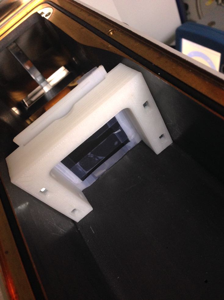
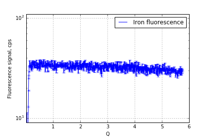
After placing this slide in the sample position, with iron foil mounted (Figure 3), we see a strong fluorescent signal appear (Figure 4). On our detector, this is about 30 counts per second per pixel, and we can integrate over about 500-800 pixels to collect many photons in a short time. The integration range can be checked with a strong scatterer in the sample position, to verify that the integration is done in the range where the absorber shields the detector from the scattered radiation.
A measurement of the iron foil fluorescence in the direct beam is given in Figure 4, showing an expected fall-off at high angles due to the larger distance from the foil to the detector plane. We have both since measured transmission factors with this solution quite a bit, but we are still completing the necessary verifications that we really are getting the correct transmission factor out. That will be in a subsequent post.
It is worth mentioning that the high energy radiation contamination contributes much less to the fluorescence signal than the copper 
Finally, this solution will not solve the side-issue encountered before (see, again, this post, in particular the last section). If you have a strong scatterer, one which scatters a significant fraction of the beam, then you need to correct for that loss through scattering somehow as a separate effect. If you do not do this, the amount of absorption you calculate will be underestimated. That is one correction for which I have not quite figured out the practical details yet.
In any case, if you have one of these instruments and a 3D printer, and want to try out this solution, the STL file for both components are here: GuideandSlide. The remaining required parts are four M4 nuts, four 10mm M4 set screws, and a thin 5-12 
Leave a Reply