

An advance publication by Arda Yildirim, one of the Ph.D. students at BAM, has come out this week. For us, this is a pretty momentous paper: it is the first paper resulting from collaborative work on the MAUS, and, indeed, the first paper to come out of the MAUS altogether. Now, the main purpose of the MAUS is to help people, and it has been helping Arda clarify and verify the structure in his membranes. Arda has been researching porous alumina membranes during his Ph.D., filling them with a variety of materials, and when we measured them, we came across some pretty interesting findings…
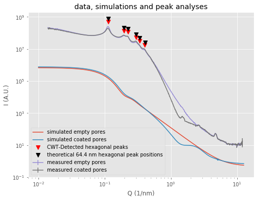
The paper is available here, and discusses what happens to liquid crystals in narrow channels. To add to his own measurements, we measured wide-range SAXS (WR-SAXS) on the bare alumina membranes as well as membranes coated with a small ODPA organic ligand (Figure 1).
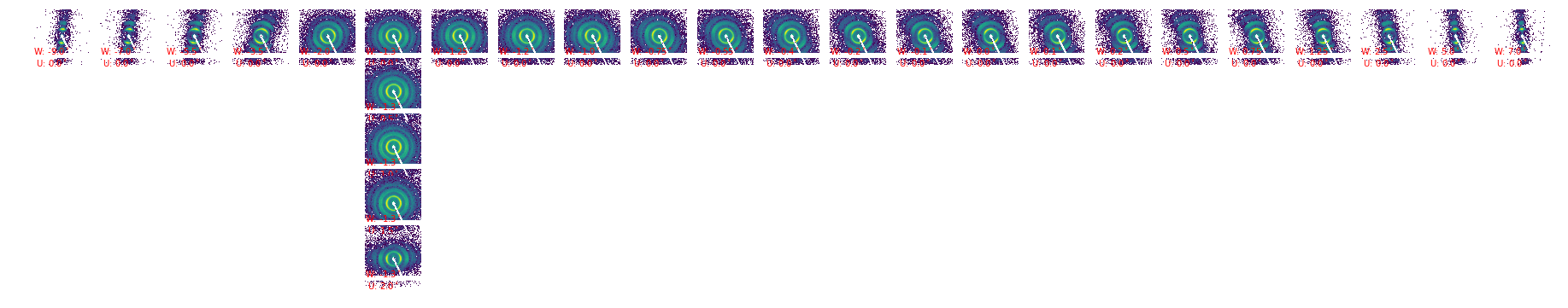
The alumina membranes were interesting to measure, as they have a hexagonal array of cylinders going (pretty much) straight through the 80-100 µm thick alumina. We checked how straight they go through, by tilting the membranes on our hexapod, and found the cylinders to be oriented approximately within 1.5˚ of the surface normal (Figure 2).
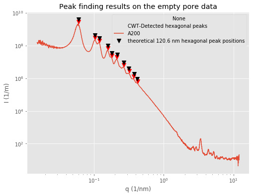
The hexagonal spacing and size of the cylinders is very uniform, and commercial variants can be obtained with different spacings and cylinder sizes, and the effects of these can be clearly seen in the WR-SAXS patterns. The hexagonal structure shows up as (up to 10) peaks on top of the scattering pattern, so we indexed and fitted the positions, which agree very well with the specified spacings of 60 and 120 nm (Figure 3).
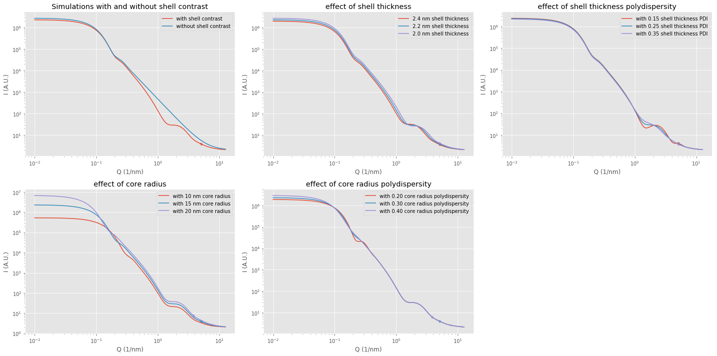
By simulating on-axis core-shell cylinders using SasView’s SasModels library, I could also assign the features that constitute the rest of the pattern (Figure 4). However, and to my surprise, I could not describe the pattern of the ODPA-modified membranes because it has features that are too steep, with a slope falling off faster than Porod’s 
Slopes less steep than that are usually (and, sometimes, too easily) considered to originate from fractal structures. Using McSAS, they can also be described as originating from dispersions of objects with very wide polydispersities, which reflects the self-similar nature of the fractal structures.
Steeper slopes are less common (in polydisperse systems), so we did a few checks to make sure we weren’t fooling ourselves with our measurements. Literature (for example this one) tells us these may come from a breakdown of one of the standard assumptions in small-angle scattering, namely that the electron density transition at the boundaries between two phases is infinitely sharp. When the electron density transition from one to the other phase is smoothened, you might get steeper slopes. Essentially, the entire curve will be convoluted with the electron density profile of smooth transitions.
Unfortunately, time limitations meant I couldn’t program a fitting function that implemented such a steeper fall-off, so the analysis in the paper ended up as a “best match” fit-by-eye effort in the end. Next time that we have a similar problem, however, we have the groundwork to go further. One step at a time…
Looks good!
Was the specimen under vacuum during measurement?
yes it was, I’ve had experience with porous materials taking up moisture from the air into their pores, and so I’m always a bit cautious with measuring them now. That’s one of the reasons I’ve got a sample chamber without the option to measure in air; it encourage you to put your samples in vacuum. If you don’t want vacuum, you have to put in some effort….