

I don’t have a whole lot of experience with Grazing Incidence (GI) geometry, indeed, I don’t have much at all. Now that we’re starting to delve into it in our lab, questions bubble up that might be interesting to investigate. For example the matter of why you need to have the sample surface in the center of rotation:
To my understanding, It is customary to ensure that the height of the surface of your sample is as close as possible to the center of rotation of your pitch stage. I have seen various solutions to achieve this, including a pack of shims included with GI sample holders, a second vertical translation on top of the pitch stage, or hexapods at beamlines (which allow you to redefine the exact point of rotation). Given the very small angles involved to rotate the sample surface to grazing angles, though, does being at the center of rotation really matter? I don’t think so, but please do send me an email if I misunderstood!
There are two potential issues I can think of when the surface is not vertically aligned with the center of rotation. These are:
- the beam shifting on the sample, and
- the beam center moving away from the center of rotation, throwing off your sample-to-detector distance calibration.
Whether this is a realistic problem can be figured out with some elementary geometry (see below). Let’s assume that, after aligning the beam with the sample surface, you rotate the sample by 0.2˚ to get your grazing incidence. Let’s also put the center of rotation a whopping 10 mm away from the sample surface. In this case, my calculation shows that:
- The beam would travel “upstream” on the sample by 17.4 micrometer, and
- The beam center would travel “downstream” before hitting the sample 17.5 micrometer later.
Compared to the finite beam dimensions, the much larger sample-to-detector distance, and the sample surface being at least 10mm long, I do not consider these values to be significant enough to warrant complicated solutions. The calculation was done as follows:
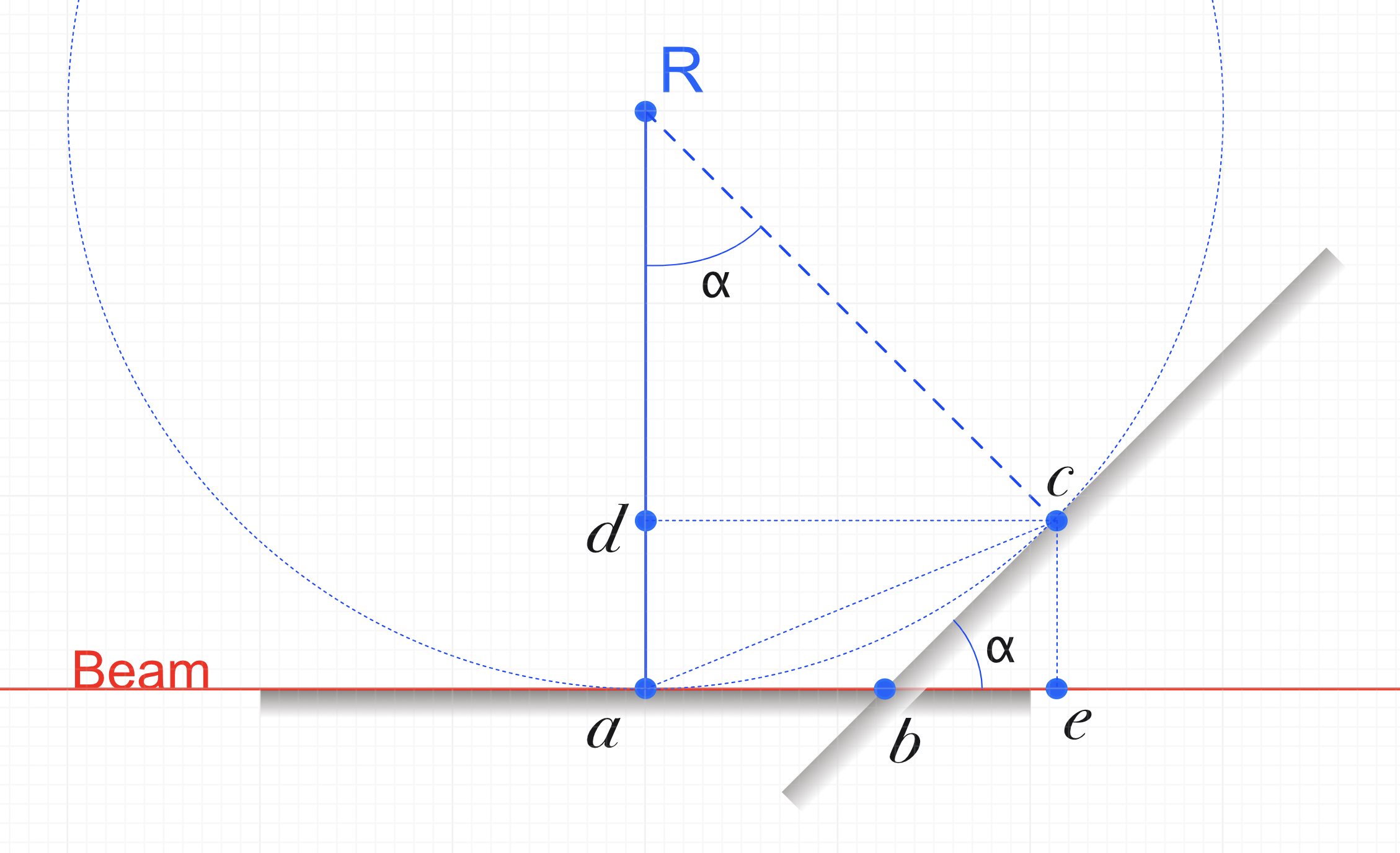
The problem setting is schematically drawn in Figure 1. The surface, initially aligned to the beam with pitch and vertical adjustments, is then rotated using the pitch stage to a grazing incidence angle 


We know that for the shift on the surface:
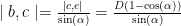
and for the shift of the beam along the beam path:

Plugging in the demonstration values, we get the values of 17.4 and 17.5 micron for the beam shifts. Realistically, you’ll even have to put in some effort to be *that far away* from the center of rotation, but with custom stages, you might rest assured that even that is unlikely to make an impact.
Now I may be wrong (and have been in the past). If you know why it is important to put the sample surface exactly in the center of rotation of your pitch stage, please do drop me a line. Contact details are in the “about” section.