

A great many of the data correction issues in small-angle scattering can be resolved by trading a kidney for a PILATUS detector [1] (or similar [2]). These are detectors using a single crystal sensor as detection surface, and have extremely low noise, low distortion, high dynamic range and single photon sensing capabilities. However, as investigated by Gollwitzer and Krumrey (arXiv version here), this type of detector we so adore for its good detection characteristics may need a bit more data adjustment than expected.
The basis for the problems is the Bragg reflection occurring in the crystalline structure of the detection surface. There is an increased chance for this crystalline reflection to happen when the conditions are right, i.e. when a photon of a certain energy impinges on the surface at just the right angle. If this is the case, the chance for the incident photon to be detected is reduced by the probability of Bragg reflection (in which case it is not detected).
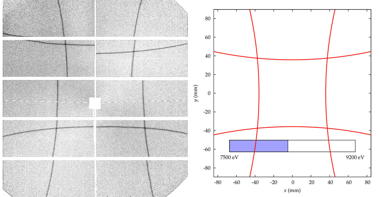
What you then end up with in a given SAXS measurement, is the reduction of detection efficiency on specific lines on your detector. Evidence for these lines has been shown by the aforementioned authors, who noticed a local reduction in efficiency on the order of 10% (Figure 1). This phenomenon is very energy- and geometry-dependent, and has been mapped for a variety of energies. There are also cool videos of this energy scan available on Cristian Gollwitzer’s website.
The method they used to find these patterns is similar to that discussed in my review paper for collecting a flatfield image: measure a sample with mostly uniform scattering, and compare the local response on the detector with the average for that given angle. Gollwitzer and Krumrey furthermore used this to reject pixels with a disproportionate response, i.e. pixels whose values lay outside three standard deviations (in other words, you can use it to mask some pixels). Care should be taken, however, to separate the effects of beam polarisation and possible beam and/or sample anisotropy from the flatfield image. Furthermore, it will not be possible to collect flatfield information from behind shielding components such as beamstops and mounts.
A few points were clarified by the authors [3]:
- The built-in flatfield correction does not correct for this internal diffraction effect, as it is very sensitive to the particular orientation of the detector to the instrument geometry (i.e. if you move your detector or change your monochromator, any correction for this effect needs to be recalibrated). indeed, the built-in flatfield correction was left operational for these measurements.
- An interesting side note (though not explicitly discussed in this paper) is that the gaps between individual panels on a single module have a visibly different response despite the built-in flatfield correction. This implies that for good data accuracy, an additional (energy-dependent) flatfield correction should be measured separately (a topic to be discussed in their forthcoming work).
- It is not yet known to what degree this effect persists in the detectors with thicker or thinner detection materials. The intensity of the pattern on the detector is difficult to compute.
- Higher energies may suffer less from the internal diffraction effects, as the reflection indices are rather high leading to weaker reflections.
The authors furthermore indicate that this information can be used to determine the orientation of each detector module with respect to the experiment, and to determine the exact wavelength of the incident photons. However, the variation of the individual module orientation is unlikely to impact your angle calculation much.
All in all, this is a very nice paper highlighting some of the issues you may come across once you really start looking at (ways of improving) your data. It is certainly an effect which can be taken into account for small-angle scattering data corrections, especially when performed on anisotropic structures. If you want to get your data accurate to within 99%, this is definitely a correction to test for.
—
[1] They don’t do this. I’ve asked. Apparently they have plenty of kidneys.
[2] other detectors are available with similarly desirable characteristics, like the Medipix and PIXcel, but the PILATUS appears to be most popular in the SAXS world
[3] Personal communication (e-mail, January 31)