
")
This week, I want to talk a bit about the workflow I have in place for designing instrumentation parts. With the USAXS instrument nearly completely built now (albeit mechanically), the workflow is now running quite smoothly.
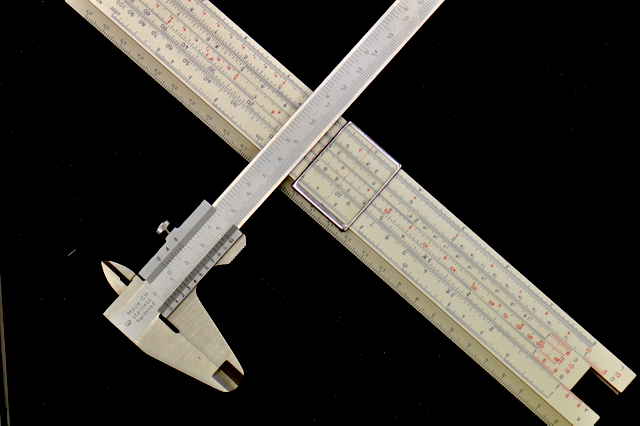
The two pieces of software I use are OpenSCAD and FreeCAD. The first I use for the 3D modeling and designing of parts, while the latter is used for the drawing dimensioning and translation to interchangeable file formats. The one piece of hardware I absolutely need are Vernier calipers* (Figure 0).
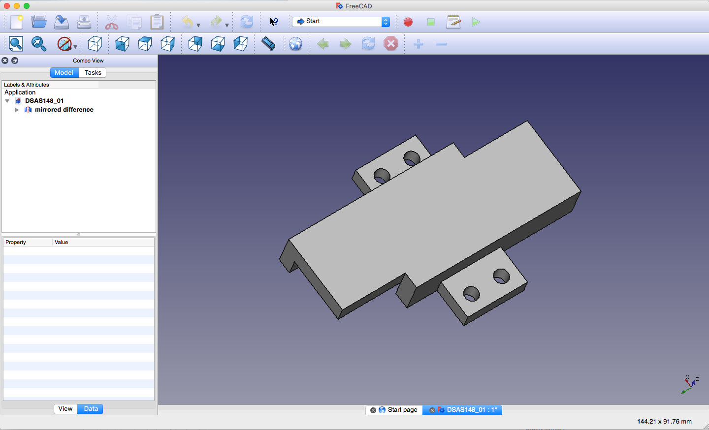
Step zero in the process is to make 3D digital models of all the components you intend to use. Bonus points if you can order the components ahead of time, so you can verify the dimensions yourself using calipers. I’ve encountered very frequently that dimensions on Thorlabs’ drawings were wrong, and even PI supplied wrong measurements on some of their linear actuators (for which they did apologise, then gave me “corrected”, but still wrong drawings, and apologised again…). At the end of this process, you should have basic but accurate outlines of your components, with the external dimensions and mounting points well defined (see Figure 1). Make sure you define your origin sensibly for all objects, and remember that this may lie outside the object. For example, for a rocking stage with a center of rotation 50mm above the surface, that center of rotation makes a damn good origin.

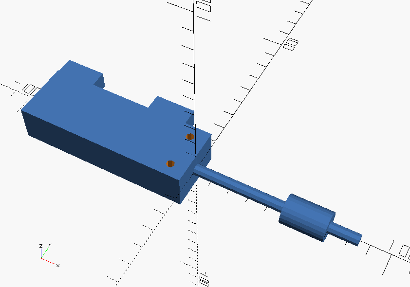
Step one is to “float” the required components in a 3D assembly model at approximately the right location. OpenSCAD allows you to do this by importing individual component or sub-assembly files in the big assembly model (using the “use” statement). Such a floating will let you see what you need to build. For the crystal holder, I float the crystal (Figure 2), and then build around it.
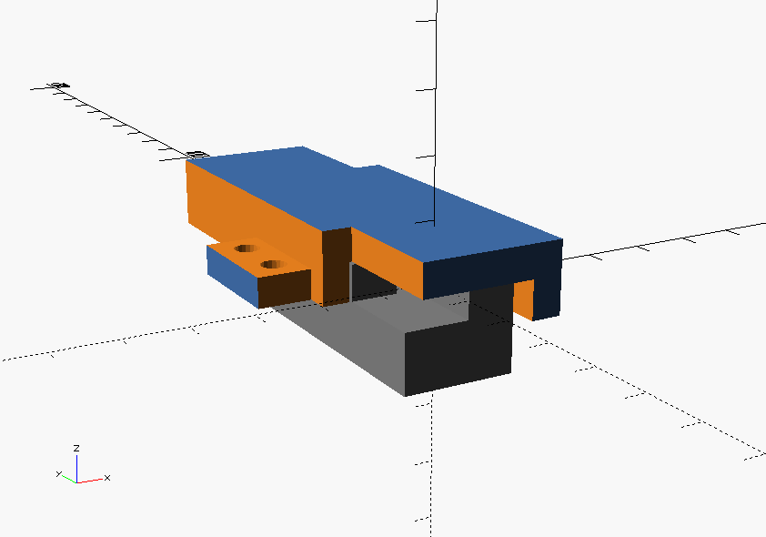
Then (Step 2) you need to design the object, keeping in mind that something as simple as a crystal holder could consist of four separate parts. It is here that time spent in the workshop shows its value: experience will tell you if something is easy or difficult to make as a single part or whether it’s best to split it into a few more parts and deal with some more screws. While designing, rotate your model assembly so you know it fits well with the floated objects you design around.
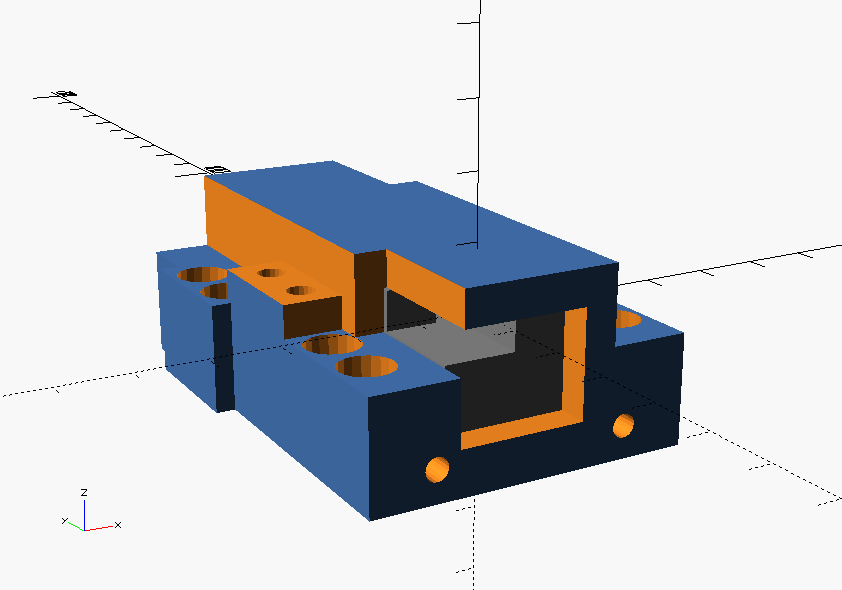
Step 3 is making sure it fits with the other parts you have designed. So add those to the 3D model assembly as well, and check that all the screw holes line up, that there are no access restrictions to screw holes of other parts, and take note that (nearly) every screw has a large head for which space needs to be reserved (Figure 4).

When you have a group of parts which can be combined to form something greater, and when the sum of those parts can be seen as a complete independent part, you move on to step 4: checking the assembly in the total instrument. Here you check if the assembly mounting holes line up with the rest of the instrument, and whether there are any unforeseen … “steric hindrances”, i.e. if there are no other parts of the instrument in the way of your grand plan of mounting the assembly in the right spot (Figure 5).
Only when you are completely happy with the group of parts, you move on to step 5: drawing dimensioning of those parts. Remember, adjusting a radius here or a tolerance there is easier to do before you’ve drawn it all up. FreeCAD opens most OpenSCAD objects without any issue (although it has some problems with the “hull” operation, so avoid that). In order to get the drawing dimensioning functionality in FreeCAD, you just download the module and put it in the right place in the FreeCAD directory structure.
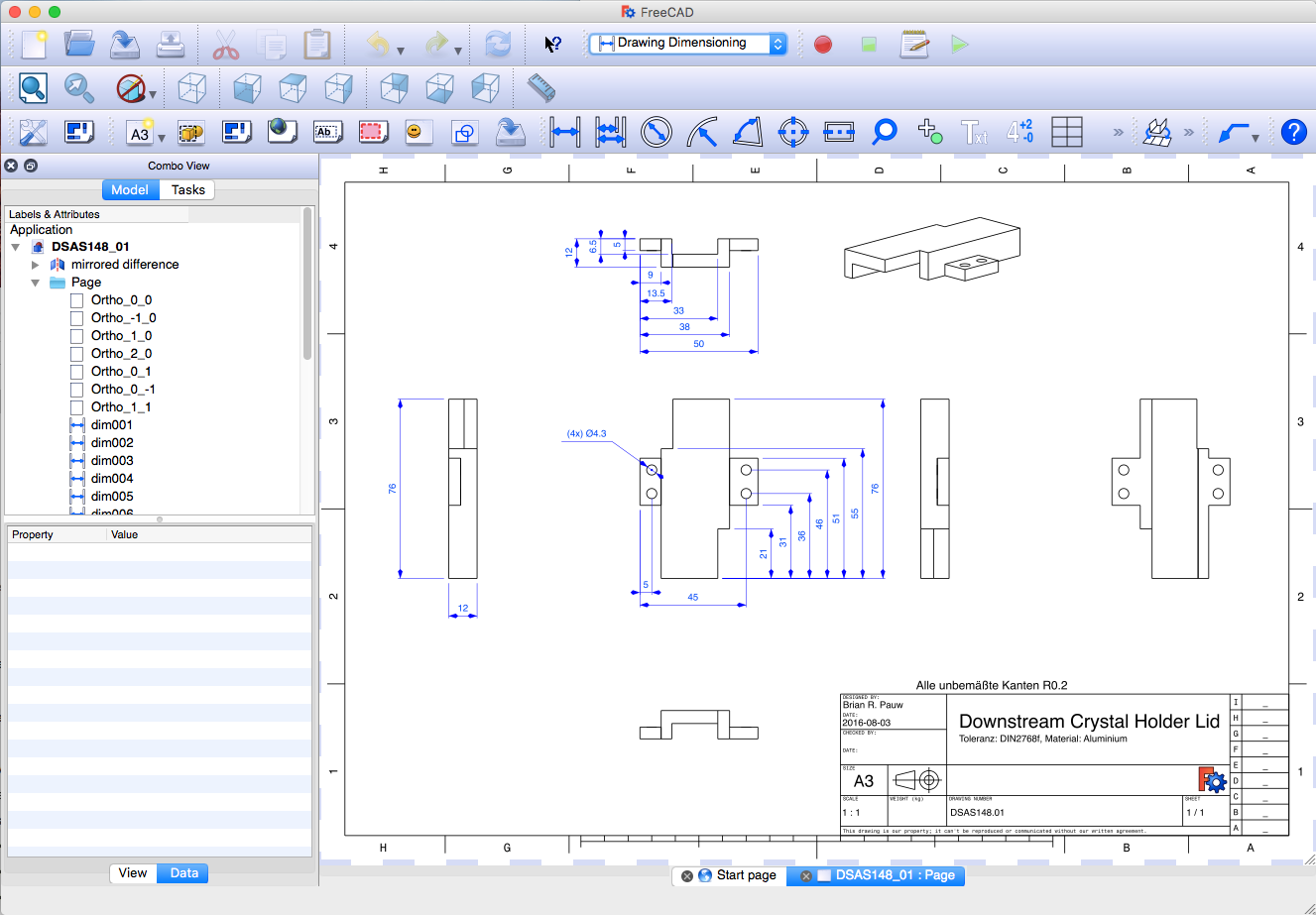
The drawing dimensioning process follows some rules and conventions which may be location-specific. If you are not sure what conventions are adhered to in your case, dimension a simple object and discuss with your workshop staff whether it is correct. The projection convention in Figure 7, for example, turns out to be an American one, which (of course) is not used in the civilized world.
Step 6 is to export the 3D model from FreeCAD to some other formats which the workshop can use (we typically export to IGES and STEP formats). They can directly use these in CNC machines where necessary, or use them as a reference in case of questions. Do this to easily improve the life of your workshop staff.
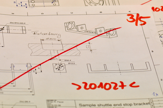
In Step 7, you take your drawings and discuss them with the workshop staff. In this dialog, you end up discussing all sorts of details, mostly to specify if modifications of the design are possible to make manufacturing easier. In many of my designs, a radius tolerance is added so that the milling process can take place without having to reorient the object in the mill. Deciding to allow or disallow such modifications can be difficult in the beginning, so it helps if you bring 3D-printed models of your parts along as well. I don’t do this anymore, but this was very handy in discussions in the beginning. In the end, the drawings coming back from the workshop (Figure 8) have many different markings and notes on them than they did in the beginning. Read these and use them to improve your future drawings.
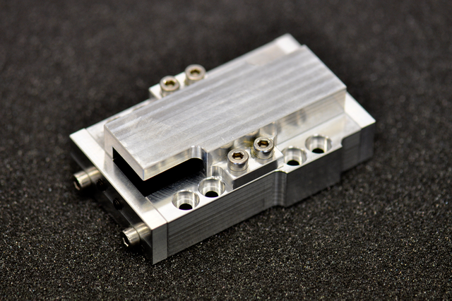
Step 8 is the waiting… In our workshop, it usually takes about four to eight weeks. There are those who balk at such a waiting time, but having spent time in the workshop makes me realize that is actually quite a good turnaround time. Especially considering the quality of what comes back afterwards (Figure 9), and having the pleasure of assembling it, noting that it fits exactly as intended!
Step 9: When all is done, bring the workshop staff a few beers. This is essential in any design workflow.
*) Regarding Vernier calipers: If you haven’t got one of those, and want to get one, my one recommendation is to get an analog variant. Do not be fooled into thinking the digital ones are handy; the digital ones will run out of battery and (despite your best new-years-resolutions) will remain in your drawer until its innards are corroded with battery acid. You need calipers which work the instant you take them out of your drawer, and only an analog one has this feature. Don’t trust me, ask around in your workshop what they use. Chances are they’ll show you a digital one, realize it doesn’t work, and pick up an analog one.
Leave a Reply