

While I was under the assumption that we’d test the Bonse Hart USAXS instrument at the synchrotron first, scheduling issues there have dictated that we should test it in our lab instead. This means that I need to build the control electronics. Here’s the plan…In total, we have to control 12 stepper motors, 3 pistons, and read out two encoders, two pressure sensors, and one detector. For the motors we use two six-axis Trinamic controllers, which need to be addressed using RS485, while most of the remaining components use RS232 or return analog signals. Figure 1 shows the connection diagram.
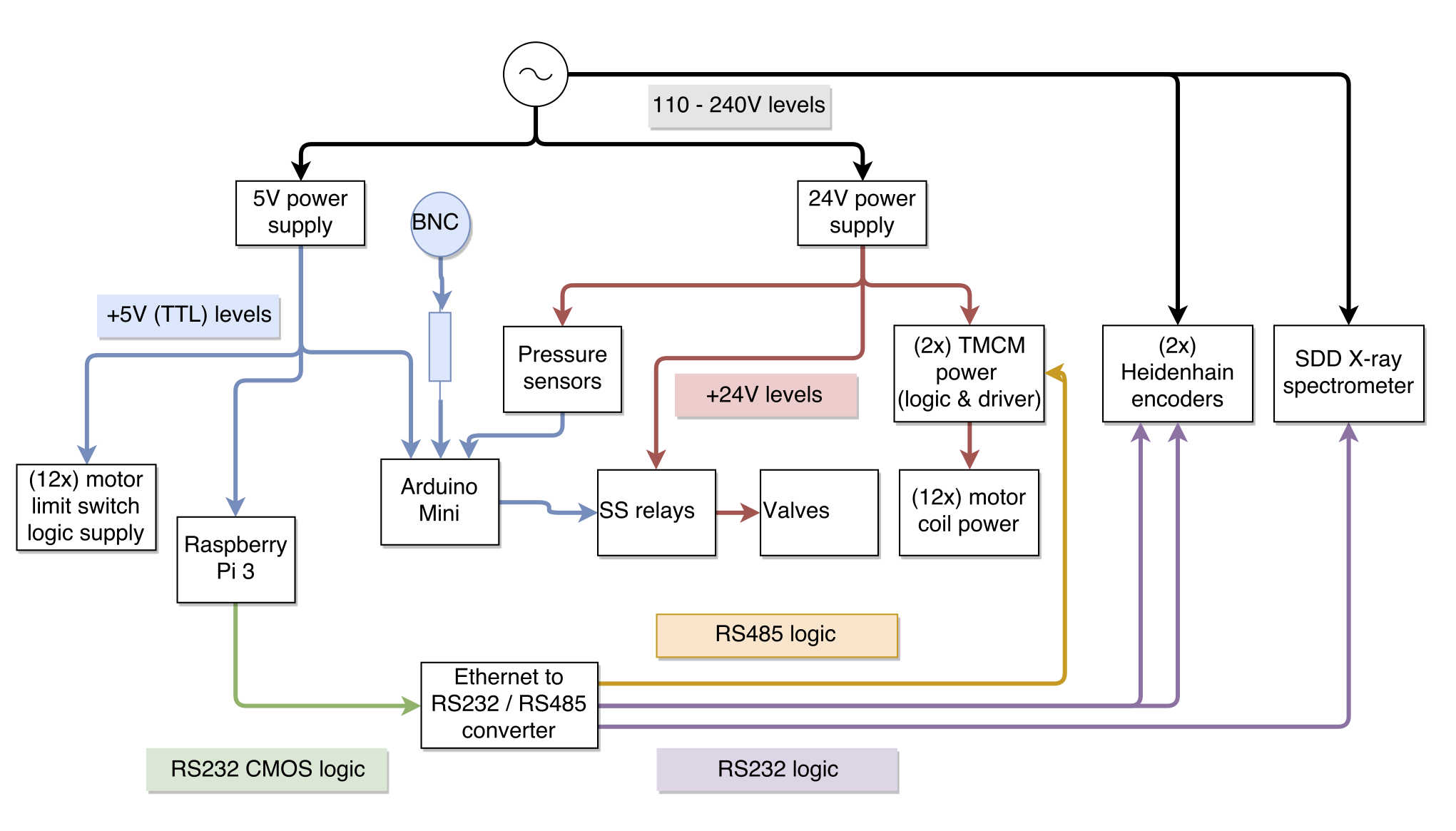
To deal with the pneumatics and pressure sensors, we use an autonomous Arduino Mini, with a single input signal to set the desired state of the pistons. The control of the motor stages, and the read-out of the detector will be done by a Raspberry Pi 3, communicating over TCP with a four-port Ethernet-to-RS232/485 converter. I’m still trying to decide what’s best for controlling the instrument: using my previously self-written control software, or switching to (perhaps) Tango. Though perhaps that won’t run on the Pi..
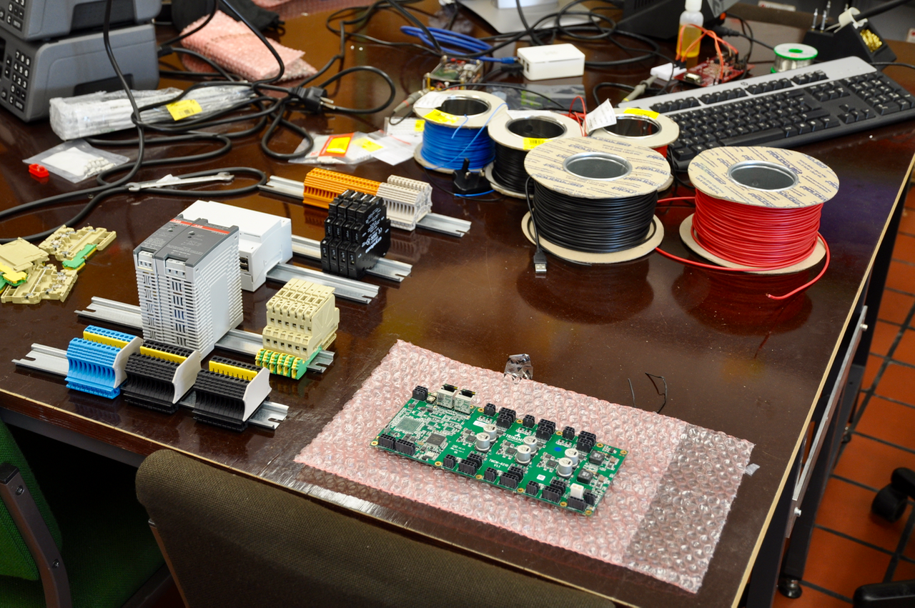
The remaining trouble is just making sure that everything gets the power they need, and that I don’t mess the wiring up too much. Like before, I’m sticking as much as I can onto DIN-rails (Figure 2). This is not compact, but offers a very good pseudo-breadboarding platform for development systems. This time, I also found bridging bars for the terminal blocks, which can connect up to ten blocks at a time. Ideal for those power- and ground lines!
Now, we also connected our Red Pitaya to a second Raspberry Pi, just visible in the back of Figure 2, and is our debug-oscilloscope (and spectrum analyser). Hopefully, we won’t be needing this too much, but it’s a nice addition to have.
As for the detector, we have two: one PIN-diode for synchrotron work, and one Ketek SDD for lab-work. To avoid the interoperability issues we encountered last time, we went for a complete SDD system this time (with stable power supply and pulse processor), and should be working out of the box. Once that arrives, we’ll play around a bit and see what’s happening.
See you then!
Leave a Reply