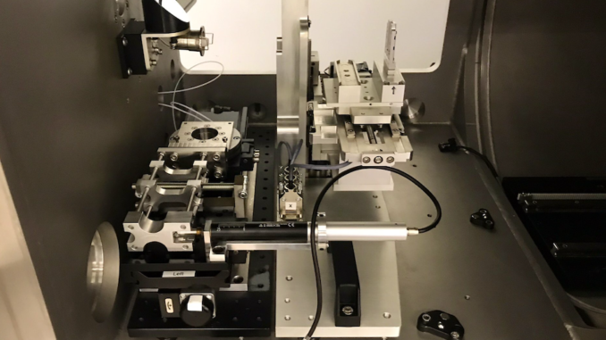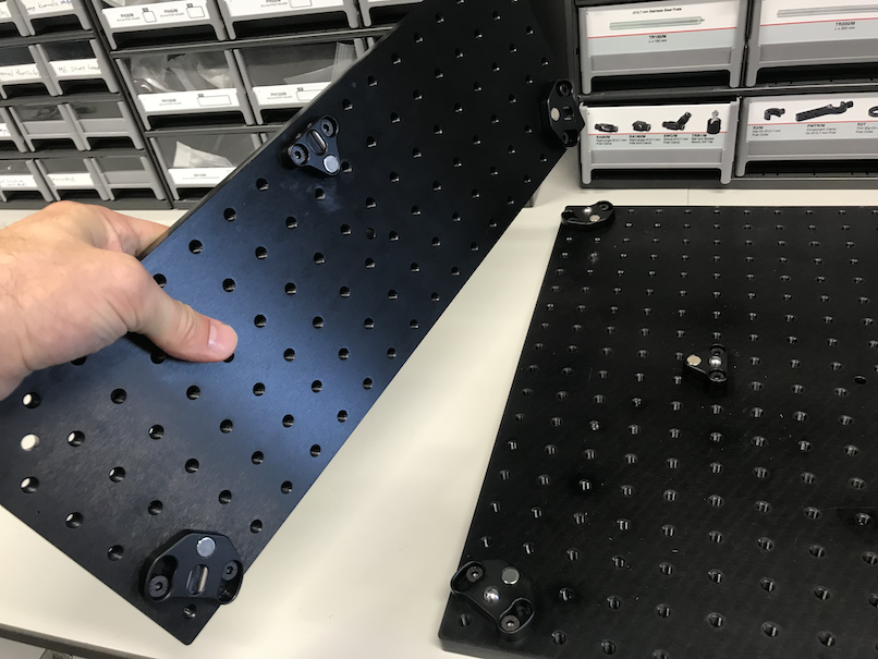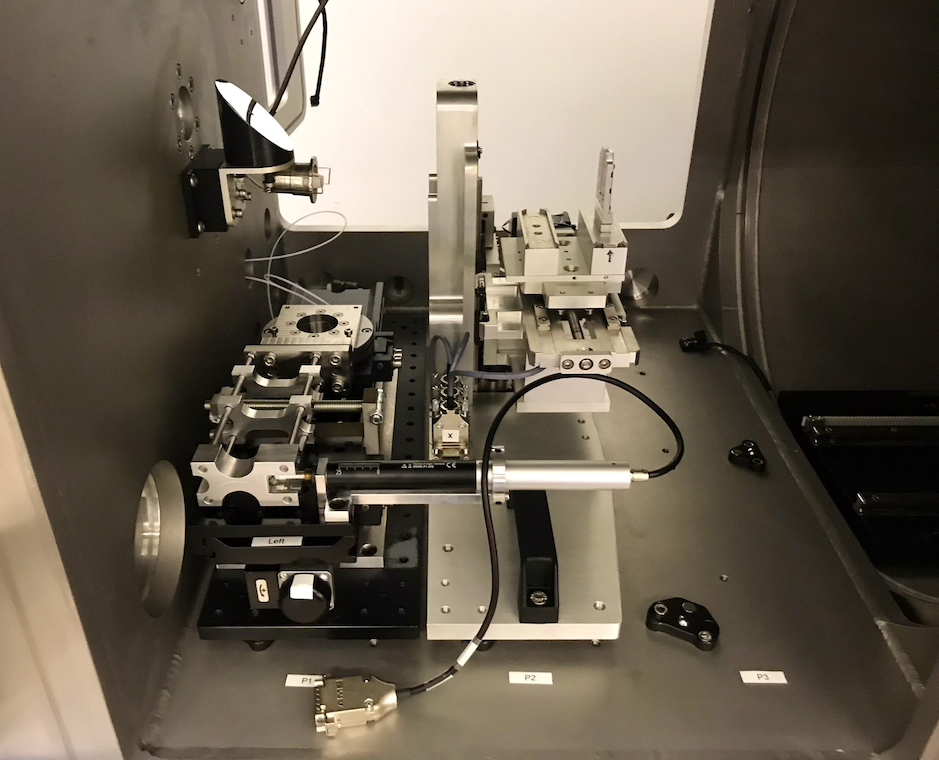
When the MAUS was built, one of the brighter things that was installed were three set of kinematic feet in the sample chamber. They were spaced so that a standard breadboard plate of 450 x 150 mm could be seated easily and very reproducibly. This has proven its worth, so here I am, waxing lyrically about them (with pictures), showing the benefits, and where there’s room for improvement. With the same plates being used in several places at the Diamond Light Source, perhaps it’s time I told you a bit about them…
One of the nice aspects of SAXS is that you can measure your sample while you do something to it. You can put your sample in an oven and heat it up, you can pull and stretch your sample in a tensile stage, you can put magnets around it and see the structure align, or even moisturize or dry it up.
For all of these, however, you need a special sample rig. Over the years, many such rigs have been developed and published about, including this one, which is one of the stranger ones I’ve made during my Ph.D. many years ago. Placing these on a beam line or in a SAXS machine, however, often requires custom adapter plates and brackets, which is an annoying and thankless job to make. Similar mounting problems exist for pretty much every sample holder in the book, from large ovens and tensile rigs to small flow cells.
So for the MAUS, we wanted an easy, flexible and highly reliable way of mounting these sample stages. As the sample chamber is the nexus of all applications of SAXS, the sample environment needs to deal with everything we throw at it. So, flexibility is of the essence.

As v3 of the USAXS was conceptualized (in collaboration with Diamond’s I22 beam line and the ESRF DUBBLE beamline), it focused on an easy-to-install, modular concept. Therefore, using optical breadboards was a no-brainer. With the optical breadboards, you have a more-or-less-standard platform on which many things could be screwed in*. Indeed, many synchrotrons use optical tables already to mount the sample stages onto. For the v.3 USAXS, we settled on a commercially available plate measuring 450 by 150 mm. The USAXS needs three, so the sample chamber was equipped for three such plates, side by side (with the short side parallel to the beam). These are then supported by the three kinematic feet in the corners and middle **), allowing a good deal of weight (with the center of mass in the triangle subtended by these positions).
Since their installation, the plates have been a cornerstone of our work; they allow us to move sample stages around the sample chamber, and install new ones (such as the hexapod) easily (electrical connections are not passed on via the plates, but need to be connected separately). That does mean we have a few positions the sample plates could be in, but our measurement methodology can deal with this easily.
We now also have a laboratory in which we can spend some time developing new plates, and it is here that the current MAUS-compatible USAXS v3.1 adaptation is taking place. Fortunately, there’s not much that needs to be done for that.
Now, I know what you’re thinking: For many sample stages, this plate might be overkill. For other stages, maybe it isn’t quite enough. So I think this plate should be considered a size M. I will get into size S later.
Since we had three 150 plates side-by-side, I thought it would be possible to insert an L-sized plate for oversized sample environments, measuring 45 by 45, this one to be precise. Today, we mounted some feet on this plate, but alas, the space left in between the three plate positions meant this was not meant to be. Sources at the Neutron facilities, however, tell me that my idea of L isn’t quite Large enough. They’re talking pallet-sized multi-ton-weighing sample environments. Again, we find everything’s bigger with neutrons. I also do not know what the maximum weight load is of those kinematic feet, but I doubt it’s large enough for Them.
However, the success of the plates makes me a great proponent of proposing this as an international standard for sample environments. They’re easy to set up for a given environment, everyone can get them, and the many threaded holes in the top should be enough for everyone…
*) permanently, if you use the wrong imperial threads. Fortunately, Diamond mostly follows common sense and standardized on metric for everything.
**) I don’t always understand optics people. Here we have these fancy, high precision kinematic feet, and yet two out of three have such an enormous amount of positioning freedom that I’m left wondering if the optics people position their stuff using nothing but stone tools and crayon. Secondly, there’s these optical rods. You know the ones: they always unscrew themselves when you look at them wrong, and you can never quite get enough rods in place to make an actually *rigid* structure… So anyway, the two way-too-tolerant kinematic feet have been mounted in that particular rotation visible in Figure 1, so that we have a standard.


Leave a Reply