

This’ll be a relatively short blog post on something we’re developing for an upcoming beamtime, and how (the lack of) open hardware licensed designs drove us to this direction.
The furnace
The requirements and alternatives
In 2.5 months, we’re having USAXS/SAXS/WAXS beamtime at the Diamond Light Source for a project with other BAM colleagues. For this beamtime, we need to heat a sample up (stepwise) to 1200˚C in air for at least a few hours in total. The normal solution for this is a Linkam stage, who have options for 1200 and even 1500˚C. These, however, are challenging to use with vertical sample mounting (i.e. when used with a horizontal beam), and if I understand right, should be used with an inert gas above 600 degrees C.
After some searching, I did find a peer-reviewed paper with a modern design. This would have to be adapted a bit for our purpose (as usual for hardware), but unfortunately, while the paper was publicly available, the design documents and drawings are not. Other options available at the beamline were generally very bulky and would radiate too much heat to the surroundings on prolonged heating. None of these would be the MOUSE either for future use. So to the drawing board we went.
The design
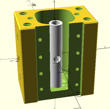
We settled on a design around a heating coil wound from 1 mm diameter Kanthal wire. This wire is stable at high temperatures (their A-1 wire can be operated continuously in air at 1400˚C, but even the cheaper variant we have goes to 1250˚C). This we will wind around a small ceramic tube that will serve to more evenly distribute the heat and form a nice tube-like cavity for the sample mounted on a thermocouple or in a suitable capillary. The small dimensions mean that we can get away with much lower power, which also dramatically reduces the cooling demands.
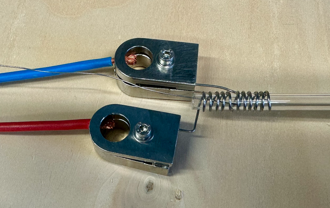
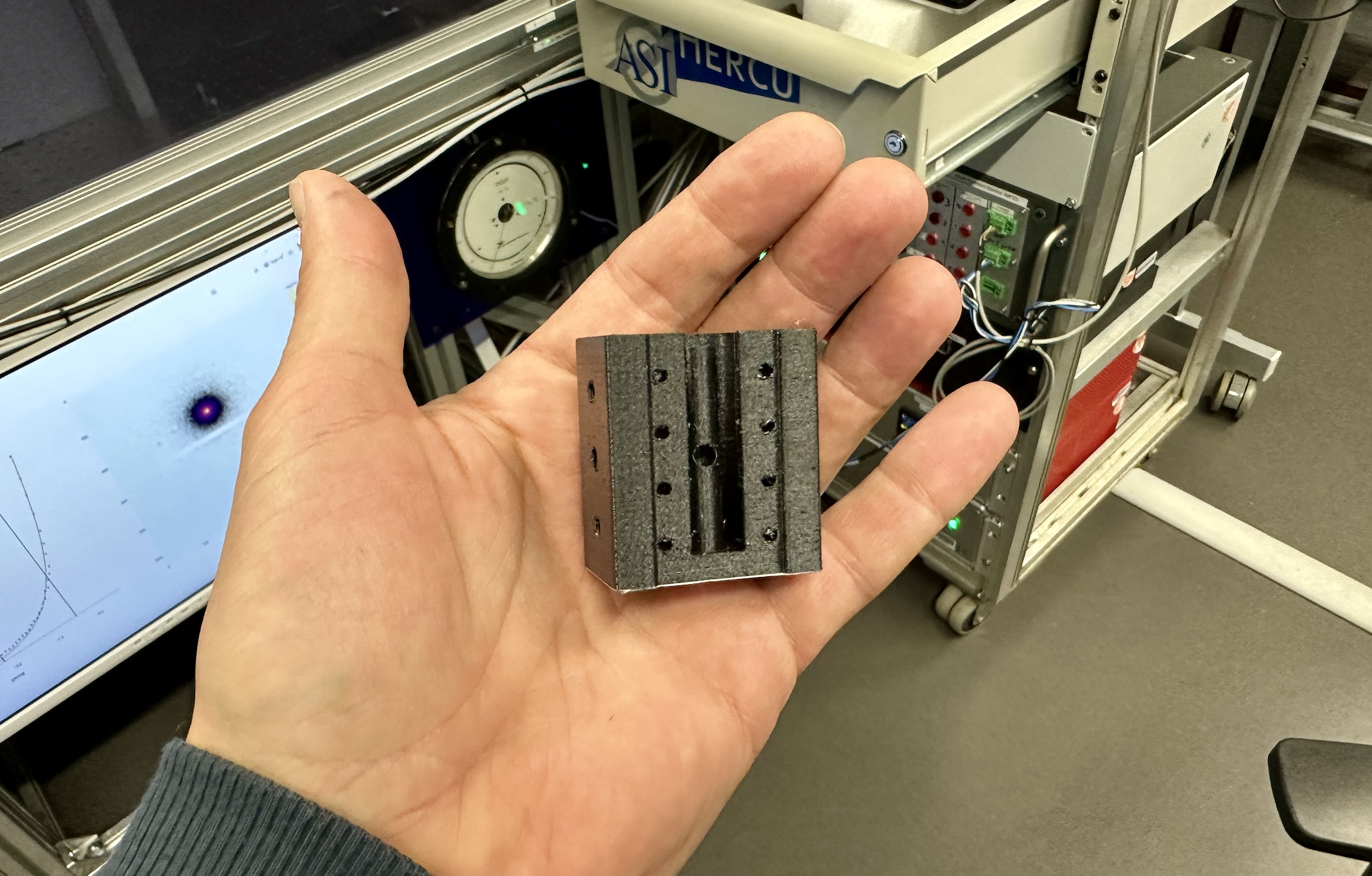
This heater will be mounted inside a compact, CNC machined, water-cooled sleeve, with all connections on one side for convenience. There will be replaceable exit apertures on the downstream side that can be adapted to the application.
We will rely on a recycled, adjustable DC power supply for the heater with a maximum voltage and current of 35V, 45A. Using such a power supply improves operational safety at the cost of having to deal with somewhat higher currents. One advantage of using a DC power supply like this is that we can use proportional control from the temperature controller instead of the standard on/off heating. This should be much more gentle on the hardware and allow for more accurate control.
For control, we’ll be using a Eurotherm temperature controller with a proportional output and N-type thermocouple input available at Diamond, tied into the EPICS machine control network. The sample will be mounted on the tip of an N-type thermocouple, which should provide stable readings close to the sample even at higher temperatures and in non-inert atmospheres.
Initial tests
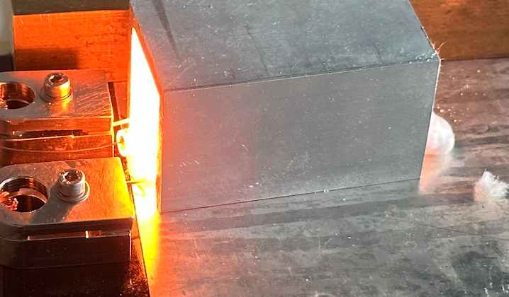
To make sure this would work, we wound a small coil (11 windings, ~20mm long, 7 mm i.d.), and tested whether we could reach the temperature for a few minutes (taking appropriate safety precautions). Using a DC power supply, we could stably and repeatably reach 1200 degrees, requiring 15V, 20A, for a total of 300W. Cooling using aluminium around it, and insulating using ceramic wool proved very effective as well.
Once the sleeve has been made and the ceramic tube has arrived, we will continue with integration tests to see the effectiveness of the aluminium water-cooled sleeve.
Coming up
We have put effort into finishing this design well in time, so we can take our time to properly treat the wire on a few prepared coils, and iron out any issues that will probably come up. At the same time, a sample holder is being made that fits on the tip of the thermocouple and inside the ceramic tube. The ceramic tube also needs some extra holes for the beam to go through, so I’m relying on the special capabilities of our workshop to make this happen.
And then it’s going to be a great experiment. Lastly, if successful, the oven will be used for other upcoming experiments as well. The designs will be made available under a CERN open hardware license, so that others know under what conditions they can adapt and reuse the design (just like how we license our software and papers). To be continued…