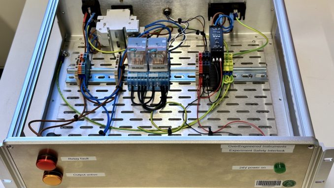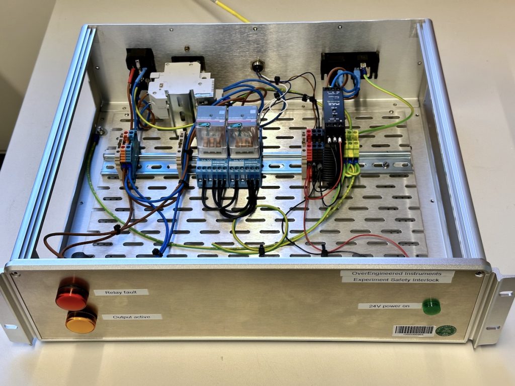
Recently, we’ve had to tighten up safety on the MOUSE, in particular for connecting high-power 230V electrically heated stages inside the sample chamber. Since radiation safety regulation here prevents me from modifying the existing safety circuit (connecting all the doors on the enclosure) without having to redo the safety check, I had to come up with something independent.
The cleanest system I have seen was for the old SAXS system at the Risoe national laboratories in Denmark. That safety interlock relied on a vacuum safety switch. If there was no vacuum, the instrument was not closed and the interlock interrupted.

So, copying that idea, I designed and built an electrical interlock that uses one of those vacuum safety switches to interrupt power to the heater circuit. It’s nothing groundbreaking, but I’ve put the electrical interlock design together with the parts list and pictures online, just in case anyone else needs an interlock system too. Highlights include:
- A double return +24V signal line, and a double relay system to reduce the risk of an incorrectly closed safety circuit.
- A warning light in case the relay state is unequal
- Complete separation between the control system and interruptible circuit
- An extra, resettable ground fault circuit interrupt and fuse on the interruptible (heater) circuit
- A creative-commons CC-BY-4.0 licensed design, with simplicity foremost.
- An additional +24V and 0V line on the external circuit, in case you need to power external interlock devices (light curtains, proximity sensors, etc).
Just so we’re clear, I’ve a chemical engineering degree, not an electrical engineering degree. I designed and built this because there was noone else available to do this. While the circuit has been blessed by our local electricians, anyone copying or modifying the design should probably double-check to make sure it adheres to local regulations. I bear no responsibility or liability for (modified) copies built elsewhere. If you do have improvements, however, please do suggest them on the Github repo! If you want to cite the current version of the hardware, there is a DOI and reference to v1.0.1 available on FigShare here.
Next up, I’ll be rebuilding the near-universal temperature controller, and I’ll put those schematics and details online as well. The old version wasn’t built so poorly, but I can do better now, so we do better now.
Thanks also to my father (also a retired engineer) for helping with the layout of the electrical safety circuit.
