

When it became time to build a new temperature controller, I wanted to build an ultimate design that could be used for (almost) everything. This is what came out (click “more” for the backstory and details).
The old temperature controller I had was one that I recovered from a junk pile, where I only replaced the PID controllers with more modern units, added some connections and connected it to our EPICS machine control network via RS485 (using the Modbus protocol). It worked well for a while, but it was limited in functionality, and honestly was a bit janky in its construction. Time to build a new one.
For the refactored temperature controller, I wanted the following:
- Support for high-power AC and DC heaters via solid-state relays (SSRs)
- Support for a wider range of temperature probes including PT1000
- Support for cooling (in the end this was not achieved as I had picked the wrong model controller)
- Proper connections and separated inputs and outputs.
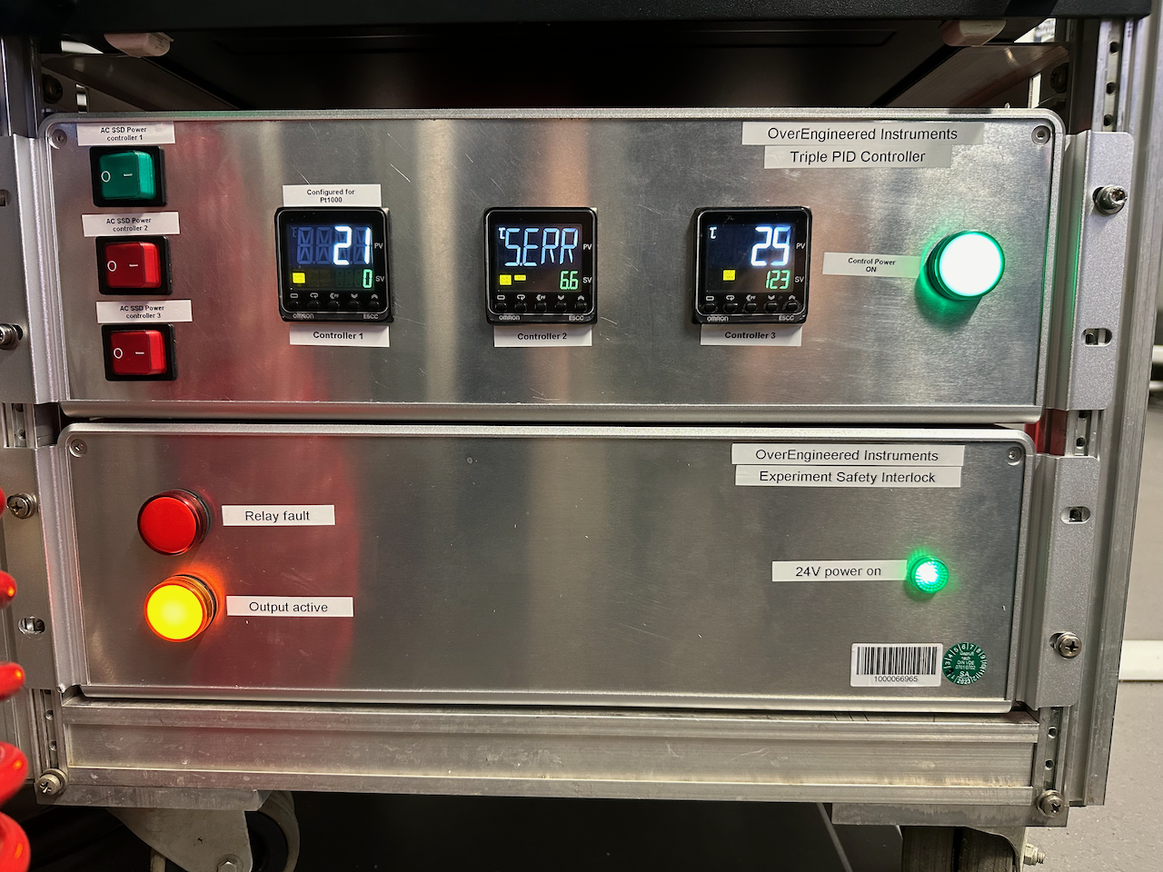
Not too complicated a list. I reused the Omron E5CC controllers from the previous temperature controller, These are reliable, capable units from a known brand but not as expensive as Eurotherm controllers. I happened to have a third, spare controller, so decided this build was going to be a triple unit. That way, you can configure one controller for each of your commonly used heating stages (provided you have no more than three), or have a stage with three temperature zones to create controlled gradients.
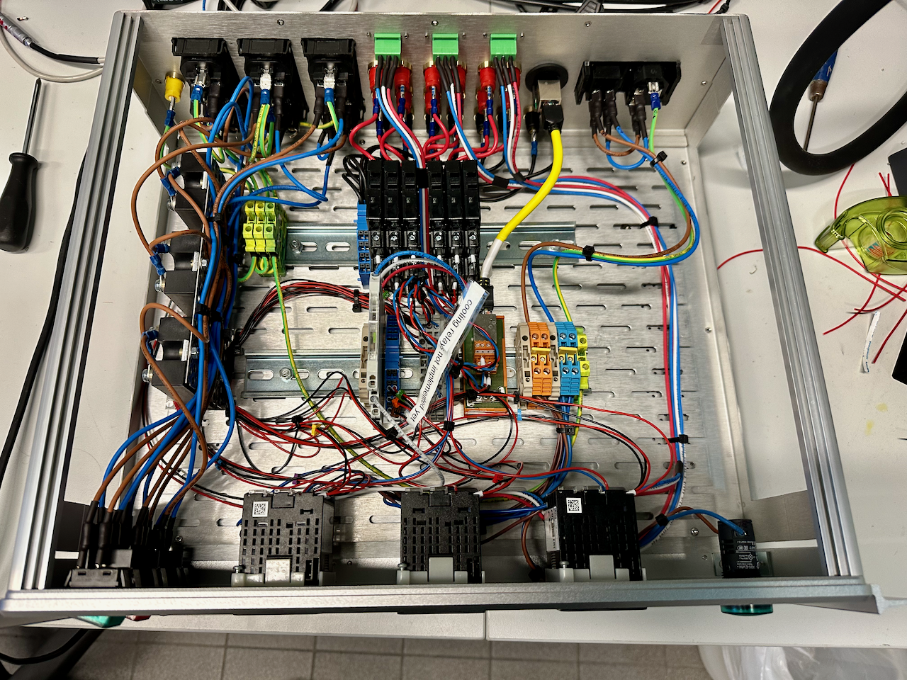
Unfortunately, I found out relatively late that I had the particular models of these controllers with only a heating control loop, and not heating and cooling control, so the (DC) cooling relays have ended up remaining disconnected until I get the need and the chance to buy the other model. It should be a simple swap though, so no big issues there.
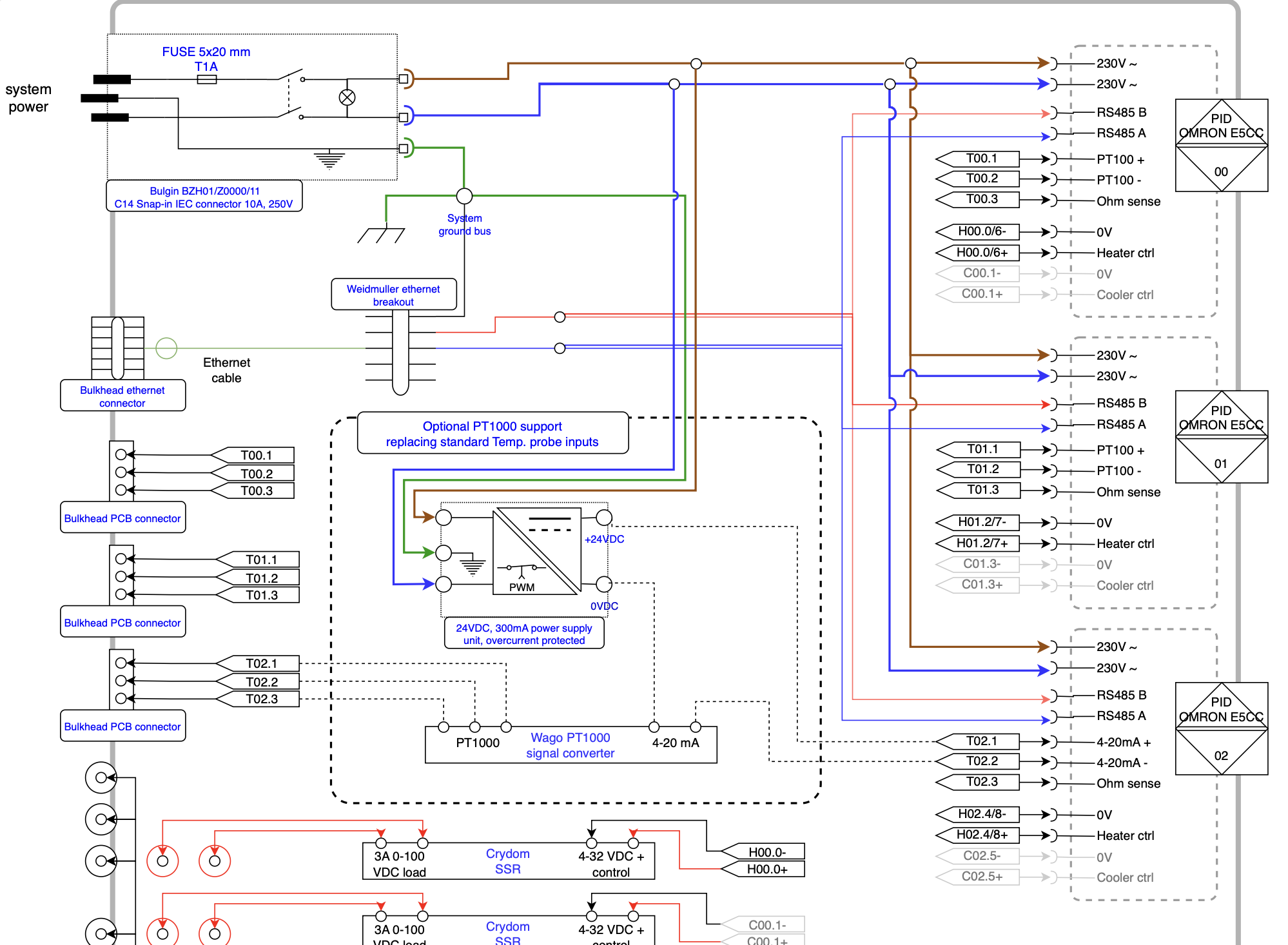
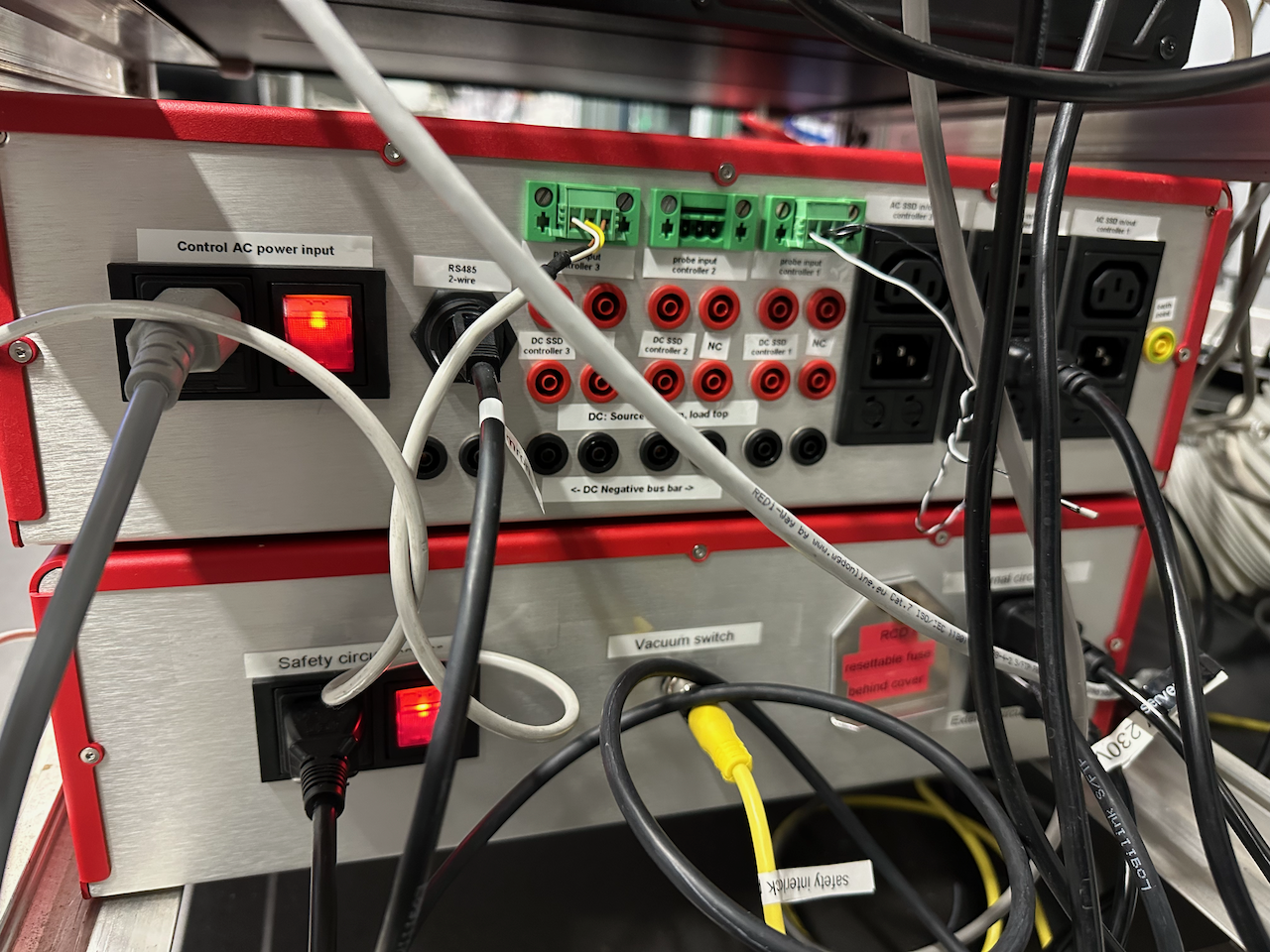
To support the widest range of DC heaters, I had struggled for a while to think about which voltage would be best, and how much power I would need to support future heaters. In the end, I decided that it was better to connect the DC SSRs directly to external connectors. So now, you can combine any external power supply of any voltage you need (5-100 VDC) via the controller to your heaters. It does mean the number of connectors at the back look very impressive, but I take that as a win.
I also wanted to be able to drive our scary ceramic Watlow “Ultramic” heaters. These are heaters that put a very high power density in a light package (with a built-in PT1000 sensor), and can heat at very fast rates. The E5CC, which supports a wide range of temperature probes, does not support that particular resistance sensor. So an additional current-loop-powered converter was added inside that converts the PT1000 signal to a 4-20 mA control signal. It supports a range of other resistance-based sensors, so that’s a nice extra flexibility. The AC SSRs are 12A SSRs, so should support heaters of over 2500W.
Of course, the controller isn’t strictly a temperature controller, but rather are generic PID controllers. So if you have the need to control anything using a PID feedback loop and on/off control (or even proportional control if you bypass the SSRs), this will work for you too. I am quite proud of the build (minus the lack of cooling control), and I hope the controller will serve us well for years to come. The general design is flexible enough to support all kinds of controllers, so if you need something like this, this design might not be a bad starting point for you.
After the electrical safety check, the controller will be ready for use. However, it should be noted that the SSRs, while fast switching, have two drawbacks. The first is that they only control one pole of the heater, which depending on how you plugged in your European plug, might be live or neutral. That means that for safe operation in exposed environments, it is recommended you connect the heaters via an electrical safety interlock like the one we designed earlier. The second issue with SSRs is that if they fail, they commonly fail closed. That means that your heater will continuously heat until the heater breaks or your sample holder melts (which is possible when built from aluminium). It is therefore also recommended you add an over-temperature safety to your safety circuit as well, with a separate sensor stuck to your sample holder. Heating is easy, but heating safely does require some thought.
The electrical design, parts list, and build photos are still being finalised, but are available at this GitHub repository.