
Many consumers (dare I say Bio-people here?) would love to have a pushbutton SAXS machine. At the moment, however, there are a few issues here that have to be taken care of. One of them is the rather cumbersome pinhole alignment procedure.
After replacing a source, realigning the monochromator crystal, or after changing of the geometry of a SAXS machine, the collimation pinholes need to be realigned. Thus, the part of the beam with the highest intensity is to be selected for this. The standard method is as illustrated in this figure:
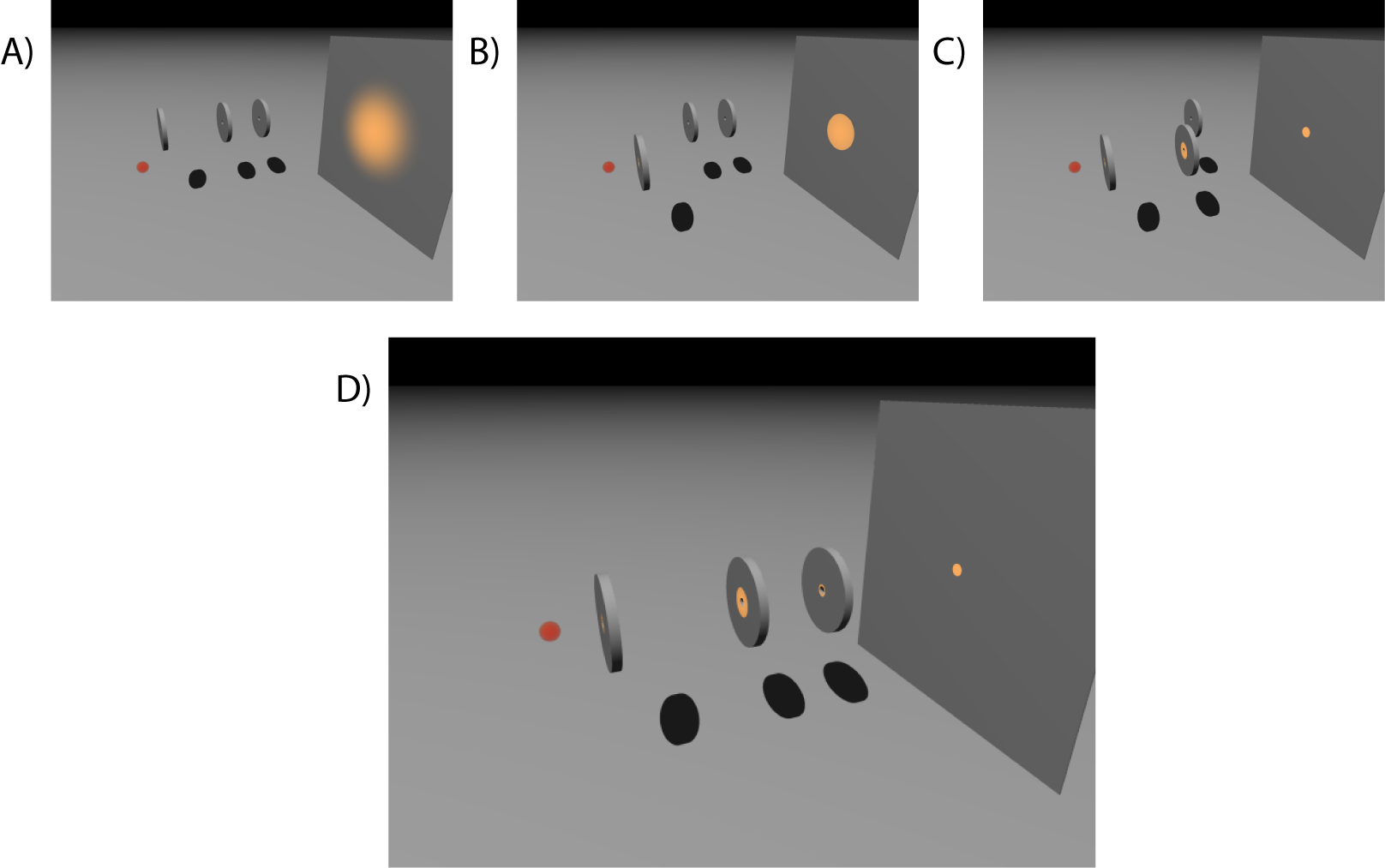
The uncollimated beam (A) produces a rather large spot on the detector. By moving in the first pinhole, most of the surrounding radiation is cut off (B). Then the second pinhole is moved into position (C), which cuts the beam into the desired shape. The parasitic scattering generated by the second pinhole is then removed by introducing the third pinhole (D) resulting in a collimated system.
There are a few issues with this method:
– If the pinhole positions are not well known, introducing pinholes two and three might become ever more tricky. This is because the only way to know where the center of the second pinhole is, is when the pinhole opening actually crosses the beam that has been reduced in size by the previous pinhole. This can get very difficult in the larger geometries, where a pinhole of say .3 mm in diameter has to be moved over a range of millimeters in two directions in order to find the beam.
– You usually find out that you moved the beam too low (for example due to misalignment of the monochromator mirror), only when you are trying to move pinhole three into position. At that point, when you can no longer move the pinhole further to center it around the beam, you have to disassemble the collimation system and realign the mirror, undoing all of the collimation work that you have done before.
– If the pinholes are aligned by the countrate over the detector, a low countrate when aligning the second pinhole may in the end cause a large error in the placement of the second pinhole. This can later, when the entire pinhole collimation system is in place, no longer be corrected (i.e. when you find out that the intensity of the collimated beam is not as much as it was once upon a time with a different collimation).
I think this could be improved using the following method:
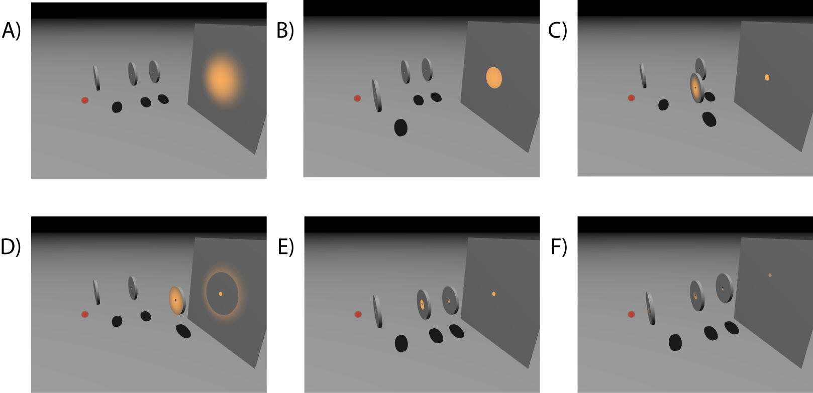
Here, the position of each pinhole with respect to the beam center and the detector is subsequently determined (A through D). Then, a region with high beam intensity on the detector can be selected, and the pinholes can be moved there, using a spherical coordinate system to move the pinholes with the source point as center. This way, an alternative position of the beam can be selected simply by moving all the pinholes in this coordinate system to cut out the new part of the beam (F) without having to realign the pinholes.
Thus, you can quickly find out if the beam is misaligned (a region can be indicated on the detector output display that all the pinholes can reach), and an alternative part of the beam can be selected. The drawback of this method is that it would require a little more than a simple counter on the detector, i.e. it would require image processing algorithms to find circle-shaped shadows of the pinholes cutting the primary beam.
More specifically, the image processing would need to correlate the center of those pinhole shadows on the detector grid, to the motor positions of the pinhole alignment motors. Furthermore, the length of the sections between the pinholes is to be measured and input in order to be able to move the pinholes around an arbitrary center (e.g. the source point) in a spherical coordinate system.
I think, however, that this method would allow for a much more robust push-button approach to the alignment of pinholes. I hope this would make realisation of a complete pushbutton system a step closer to reality. I will attempt to implement this at the Risø system in the near future.
Leave your comments at the bottom!
First of all, I am not sure that these thoughts have a very generic applicability. Your experiences with the Risø instrument are very much influenced by the problems associated with a very versatile instrument that covers a very large q-range, but requiring substantial reconfiguration when changing the resolution, as opposed to for example already commercially available instruments, set up in a fixed geometry. The latter may be regarded as essentially “push-button” instruments.
Secondly, your proposed scheme will likely not work with the Risø setup, because the divergence of the beam makes it impossible to align pinhole 2 and 3 on the raw unrestricted beam because of limitations in translation freedom.
But, your point about more advanced access to detector readout is very good, mainly because it would open for much more versatile use of the detector, e.g. by defining ROI’s.
Cheers.
Yo man… What’s all this about?