A few weeks ago, at about the same time we were swapping around motor stages for grazing incidence experiments, my trusty self-built motor controller version 1 stopped being nice. Trouble soon ensued, and so I had no choice but to try swapping this out for version 2. That version never worked properly with the MOUSE, no matter how fine it may have run on the testbed, and this time was no different. Plenty of head scratching later, and we had to suspect that version 2’s motor controller boards probably had cracks and therefore intermittent contacts. Version 3 had to be built, and post haste, as the MOUSE without sample stage motors is not particularly useful, and people are waiting for their data. So, without further ado, we started building version 3…
With no time to lose, we quickly ordered two new six-axis boards. As the original Trinamics TMCM-6210 model I used had gone out of fashion, I had to get the redesigned six-axis boards: the TMCM-6214. As a side-note, Trinamics has been bought by Analog Devices / Maxim, so I’ll hold off recommending these boards until we know if Trinamics will even survive the acquisition. The 6214 boards are smaller in size, have some odd wiring choices, different connectors, different microcontroller, and deliver a bit more than twice the maximum current to each motor coil. At least, they still speak the same TMCL control language, so a plug-and-play replacement was not unimaginable [insert foreboding here].
Things started out positive: In my collection of parts, I had a spare 19″ enclosure from RS components, a (moderately underpowered) 3.5A, 24V DIN-rail power supply, another 1.6A 5V DIN-rail power supply, and some odds and ends. A few frantic days on the RS website later, and I had most of the bits to confidently send the box off to the workshop for modifications. One week and a few back-and-forths later, and the modifications were complete, holes were holed, mounting plates mounted, and most components arrived.

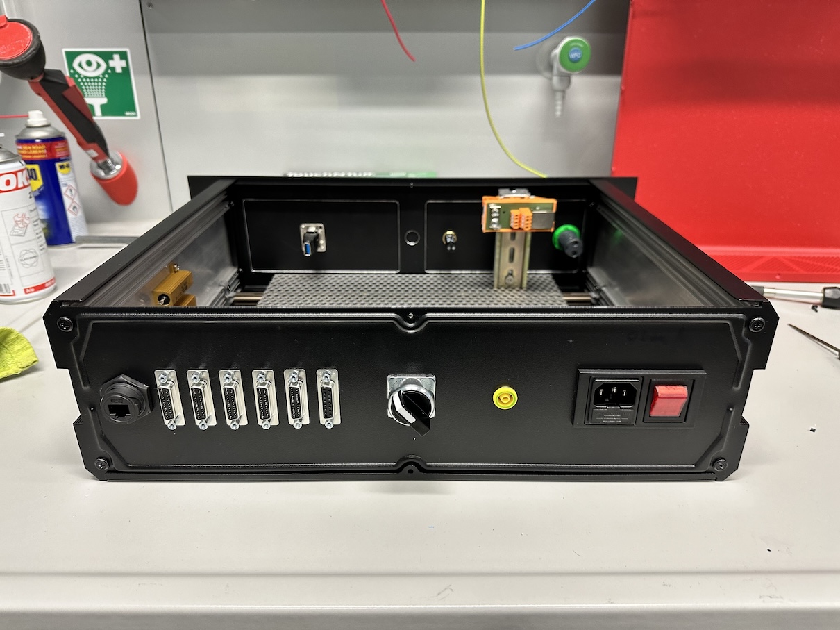
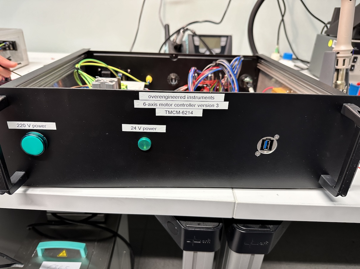
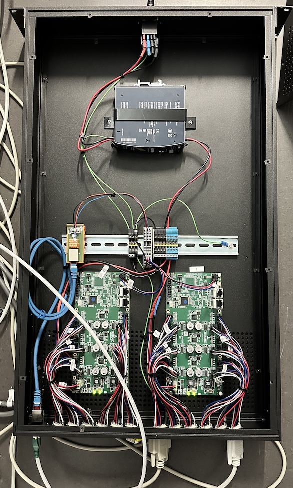
Changes from v.2 to v.3 were to space the 15-pin sub-d connectors a bit further apart, add a DC power-cut switch at the back to kill power to the boards immediately to aid swapping out cables without damage, some signal lamps to check the status and a USB feedthrough at the front so we can debug and/or configure the boards without opening the case. RS485 RJ45 jack at the back, power switch with built-in fuses and switch, it’s all pretty sweet and simple. This time, to make the system easier to build, I decided to mount only one board in this case as opposed to the previous two.
Annoyingly, the 6214 has the motor connections on a four-pin JST connector, and the limit switch connections on another four-pin JST connector. This allows for easy miswiring (which we also accidentally did, cue troubleshooting a weird voltage drop in the 24V power supply). Yet more annoying is that they moved the home switch signal to a third connector. And most annoyingly, the limit switches are now powered with 24V from the board, not with the 5V that the Newport/MKS motor stages need to power their optical gate limit switches. So that necessitated another 5V power supply brick in the system that supplies the limit switches with power. The 6210s were much simpler in this respect. Apropos, thanks to the lovely folk at MKS for getting back with specs and advice on their limit switches in a short time.
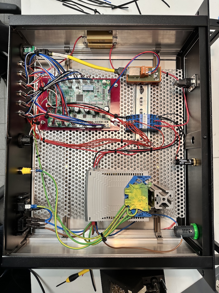
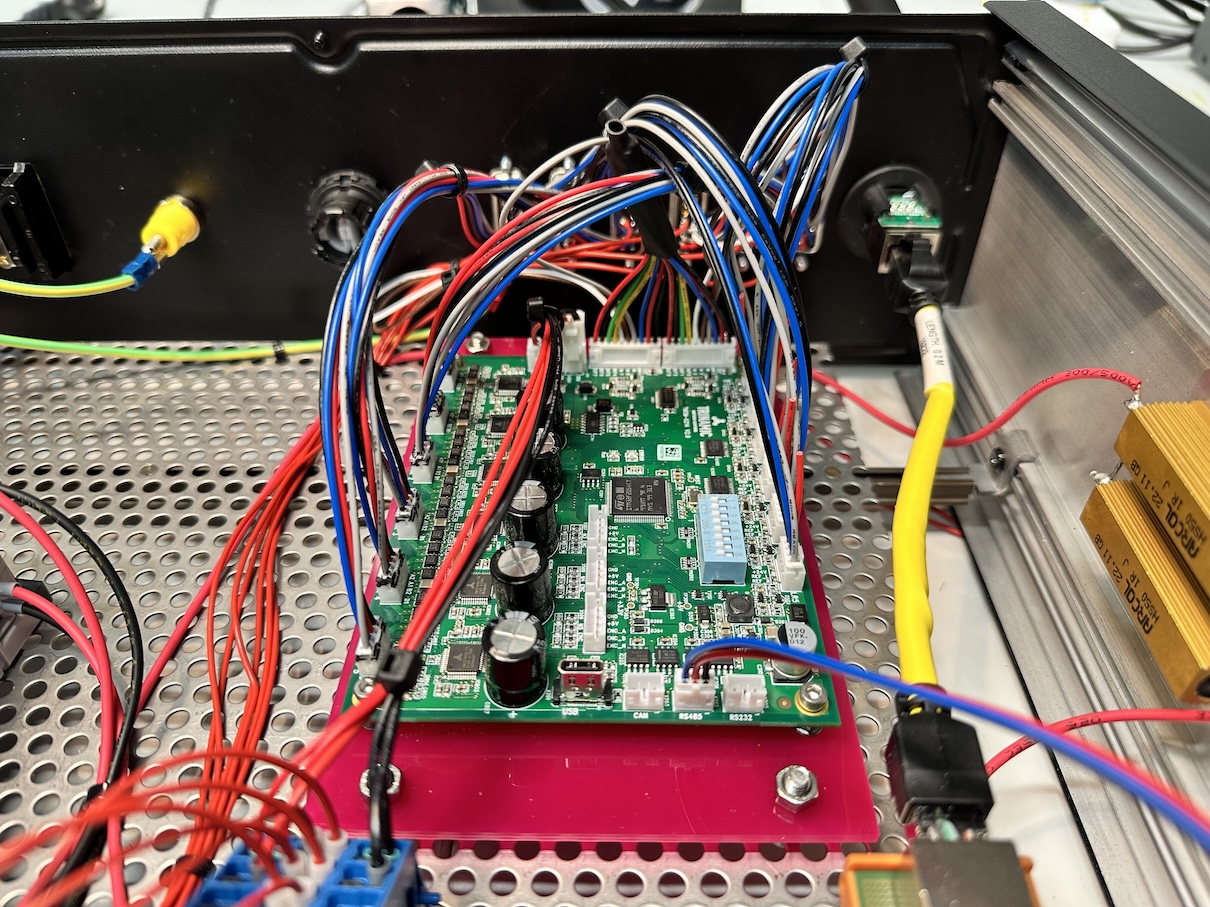
With the help of my new colleagues, we spent two days soldering and wiring up the boxes (schematics and parts lists will become available soon), and were ready for initial testing not long after. Total bulld time: a new record at about three weeks. The final wiring doesn’t look as clean as v.2 did, partly due to odd wiring choices on the 6214 boards, and partly because of a reduced box footprint.
Moment of truth: for testing, I plugged it in to the MOUSE, and… No dice. SPEC only complained about the new boards not exactly responding like the old ones did, and it being unable to control these boards or axes. Sad days.
After some testing, we found out the boards are communicating fine, and driving the motor stages fine, the problem lies in communication. So that’s the next problem to squash. Since I was eventually planning to get away from the SPEC control system altogether anyway (to an EPICS/python/Bluesky combo ideally), the most efficient direction in the long term would be to start programming this now. time to flex those “full-stack scatterer” muscles I claim to have on my CV.
Suffice to say that a few days later, I’m not quite there yet. With the aid of GPT-4 for to speed up development (and docstrings) of the more generic parts, I now have in my repository:
- a modified PyTrinamics class that can communicate using serial-over-ethernet (a pull request is in place to make this modification available in the main package)
- a robust framework for making the EPICS IOC (server) using the amazing caproto. You can also use my repository for direct control from python, though, without going through the EPICS CA communications bus.
- dataclasses (with attrs, validators, and more) for carrying board and motor parameters (using the pint package for unit conversions!), and loader and writer functions for writing the configurations to file, and
- the start of a caproto EPICS IOC for exposing some parameters to the EPICS Channel-Access bus, and some higher-level motion functions (movements with backlash etc).
This was also an experiment to see how useful those LLMs might be (or not). My initial conclusion is that it can help take care of some of the tedious tasks for generic problems. It is very good at making code look like standard code and can help to try out different structures and implement it.
That said, you need to know exactly what you want to get. You also need to be ready to spot issues and fix problems as the code suggestions don’t always work. In the end, you end up discussing how code should look like and it creates short snippets based on your suggestions. Once you get to a deeper level, like with specific caproto or pint issues, it will fail to produce reliable code, and that part is then up to you. It is handy for docstrings though. Lastly, there’s the ethical issues with taking code from a morally problematic company, who has trained their models using code gathered without consent. Should we scientists meekly condone this for convenience, or boycott this development?
The next step in this saga is to get SPEC to send EPICS commands to my new code. That will work, but we will most likely not be able to do motor scans just yet. That may just be the driver to speed up taking the next step in migrating away from SPEC.